Polishing pad and method for producing same
A manufacturing method and technology of grinding pads, which are applied in the direction of grinding tools, semiconductor/solid-state device manufacturing, electrical components, etc., can solve problems such as clogging, and achieve the effects of suppressing excessive extrusion, suppressing excessive tracking, and excellent grinding uniformity
- Summary
- Abstract
- Description
- Claims
- Application Information
AI Technical Summary
Problems solved by technology
Method used
Image
Examples
Embodiment
[0183] Hereinafter, although an Example demonstrates this invention in more detail, this invention is not limited to these examples.
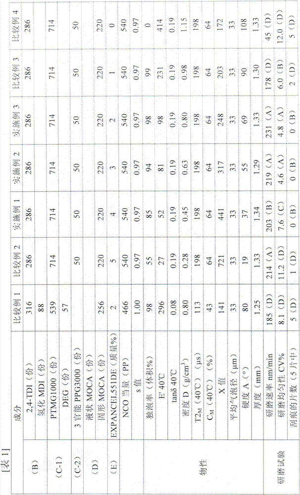
[0184] In each Example, a comparative example, and Tables 1 to 2, unless otherwise specified, "parts" means "parts by mass". In addition, the value of EXPANCEL551DE shows the mass % with respect to the total 100 mass % of all solid content, ie (B) component, (C-1) component, ((C-2) component), and (D) component.
[0185] In addition, each abbreviation code|symbol of Table 1 - Table 2 shows the following meaning.
[0186] 2,4-TDI: 2,4-toluene diisocyanate
[0187] ·Hydrogenated MDI: 4,4'-methylene-bis(cyclohexyl isocyanate)
[0188] ・PTMG1000: Polytetramethylene glycol with a number average molecular weight of about 1000
[0189] DEG: diethylene glycol
[0190] MOCA: 3,3'-dichloro-4,4'-diaminodiphenylmethane
[0191] Trifunctional PPG3000: Trifunctional polypropylene glycol with a number average molecular weight of 3000
[0192] In additio...
Embodiment 1
[0199] In Example 1, as the first component of the prepolymer, 2,4-TDI (286 parts) and PTMG (714 parts) with a number average molecular weight of about 1000 were used. The isocyanate content was 7.8%, and the NCO equivalent 540 isocyanate urethane prepolymer, in which 100% by mass relative to the total of all solid components, that is, (B) component, (C-1) component, (C-2) component, and (D) component % to 4% by mass, 51 parts of micro hollow spheres (EXPANCEL551DE) were added and mixed, heated to 55° C. and defoamed under reduced pressure. Using solid MOCA (220 parts) as the chain extender of the second component, it was melted at 120° C. and defoamed under reduced pressure. 50 parts of trifunctional PPG was used as a 3rd component, and it defoamed under reduced pressure. The first component: the second component: the third component was supplied to the mixer at a ratio of 1051 parts by weight: 220 parts: 50 parts. The obtained mixed solution was casted in a mold frame of 8...
Embodiment 2~ Embodiment 3 and comparative example 1~ comparative example 4
[0201] Various polishing pads were produced by the same method as in Example 1 except that the ratio of the micro hollow spheres was changed to that shown in Table 1.
PUM
| Property | Measurement | Unit |
|---|---|---|
| Thickness | aaaaa | aaaaa |
| Thickness | aaaaa | aaaaa |
| Density | aaaaa | aaaaa |
Abstract
Description
Claims
Application Information
 - R&D
- Intellectual Property
- Life Sciences
- Materials
- Tech Scout
- Unparalleled Data Quality
- Higher Quality Content
- 60% Fewer Hallucinations
Browse by: Latest US Patents, China's latest patents, Technical Efficacy Thesaurus, Application Domain, Technology Topic, Popular Technical Reports.
© 2025 PatSnap. All rights reserved.Legal|Privacy policy|Modern Slavery Act Transparency Statement|Sitemap|About US| Contact US: help@patsnap.com


