Copying milling cutter for processing complex cavity
A kind of profiling milling, complicated technology, applied in the direction of milling cutter, manufacturing tools, metal processing equipment, etc., can solve the problems of limited end milling capacity, large undercut, severe tool cutting vibration, etc., to reduce the residual height, reduce the The effect of small undercut and small residual height
- Summary
- Abstract
- Description
- Claims
- Application Information
AI Technical Summary
Problems solved by technology
Method used
Image
Examples
specific Embodiment approach 1
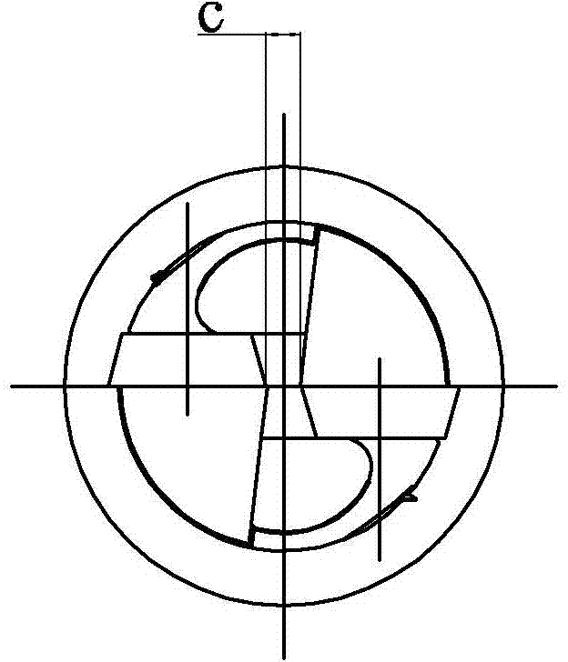
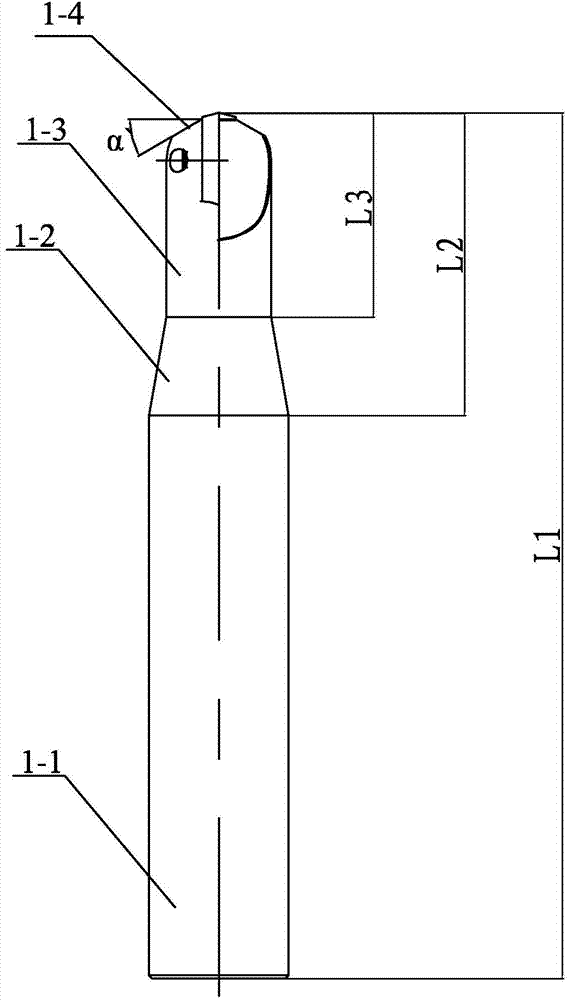
[0021] Specific implementation mode one: combine Figure 1-Figure 3This embodiment is described. A profiling milling tool for complex cavity processing in this embodiment includes a cutter body 1, one end of the cutter body 1 is provided with a plurality of chip pockets 2, and the plurality of chip pockets 2 are evenly distributed. Open, it is characterized in that: described profiling milling cutter also comprises a plurality of blades 3 with the same structure, each chip pocket 2 is provided with a blade 3 through a screw, and each blade 3 is center symmetrical structure, many The width Dc of the flat bottom between the tip of each blade 3 is 3mm-8mm, and the bottom between the tip of multiple blades 3 forms a hollow flat bottom structure of the cutter.
[0022] The present embodiment is arranged in this way, which can effectively improve the cutting conditions of the end of the tool. The end of the blade in this embodiment has no defect that the cutting speed is 0, and has ...
specific Embodiment approach 2
[0024] Specific implementation mode two: combination figure 1 , Figure 4-Figure 8 To illustrate this embodiment, each of the blades 3 in this embodiment is an indexable blade, and the outer contour shape of the blade 3 is composed of two sections of the same curve connected end to end, and the two curves are symmetrical about the center of the blade. distribution, the curve includes three arcs and a straight edge 3-4 connected in sequence, the three arcs respectively include a side edge 3-1, an arc end edge 3-2 and a rounded edge 3-3, The side edge 3-1, the arc end edge 3-2, the rounded edge 3-3 and the straight edge 3-4 are sequentially tangent, and the arc curvature radius R of the side edge 3-1 is 5mm-25mm, the arc The arc curvature radius rp of the end edge 3-2 is 0.5R, the arc curvature radius r of the rounded edge 3-3 is 2mm-5mm, the main central angle θ of the blade 3 is 30°-90°, and the side edge R The arc length is R*(90-0.5*θ)*π / 180; the secondary central angle δ...
specific Embodiment approach 3
[0028] Specific implementation mode three: combination Figure 5 and Figure 6 Describe this embodiment, the rake angle γ of each blade 3 of this embodiment is 0-9 degree, and relief angle α is 7-12 degree, and the width M of blade 3 is smaller than the radius of curvature of side edge 3-1 by 1-3mm , the blade length L is less than 2R, and the thickness s is in the range of 1.5mm-8mm. Such setting is convenient to meet the requirements of different tool parameters for secondary wasteland processing and semi-finishing processing. , to ensure the strength of the blade; in semi-finishing, the value range of the rake angle γ of the blade is 4-8 degrees, and the value range of the relief angle α is 9-12 degrees, which makes the blade sharp and reduces the cutting force. Other compositions and connections are the same as those in Embodiment 1 or Embodiment 2.
[0029] In this embodiment, the blade width M is 1mm-3mm smaller than the side edge curvature radius R, and the blade len...
PUM
 Abstract
Description
Claims
Application Information
 - R&D
- Intellectual Property
- Life Sciences
- Materials
- Tech Scout
- Unparalleled Data Quality
- Higher Quality Content
- 60% Fewer Hallucinations
Browse by: Latest US Patents, China's latest patents, Technical Efficacy Thesaurus, Application Domain, Technology Topic, Popular Technical Reports.
© 2025 PatSnap. All rights reserved.Legal|Privacy policy|Modern Slavery Act Transparency Statement|Sitemap|About US| Contact US: help@patsnap.com


