A Layered Slicing Method Based on Selective Laser Sintering

A technology of laser sintering and layered slicing, which is applied in laser welding equipment, improvement of process efficiency, image data processing, etc., can solve problems such as low molding efficiency and error of molded parts, improve precision, improve production efficiency and production The effect of quality and guaranteed molding speed

Active Publication Date: 2016-01-20
安徽中科春谷激光产业技术研究院有限公司
View PDF9 Cites 0 Cited by
  • Summary
  • Abstract
  • Description
  • Claims
  • Application Information

AI Technical Summary

Problems solved by technology

This method is relatively simple and easy to implement. However, when the selected layer thickness is relatively large, it is easy to cause large errors in the formed part. When the selected layer thickness is small, the precision of the formed part is high, but the forming time is shorter. Longer, lower molding efficiency

Method used


Image

  • A Layered Slicing Method Based on Selective Laser Sintering
  • A Layered Slicing Method Based on Selective Laser Sintering
  • A Layered Slicing Method Based on Selective Laser Sintering

Examples


Embodiment Construction

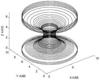
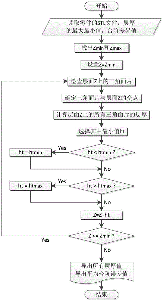
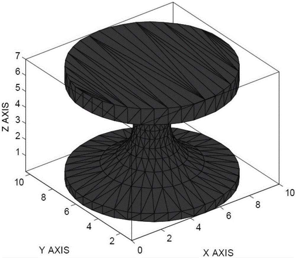
[0038] Such as figure 1 , 2 , 3, and 4, a layered slicing method based on selective laser sintering, comprising the following steps:

[0039] (1) Read the STL file generated by the CAD part drawing to be processed;

[0040] (2) Determine the delamination direction, the maximum and minimum values ​​of the delamination thickness, the maximum value of the step error and the maximum value of the surface roughness;

[0041] (3) slice the triangular face in the STL model in the layering direction for the first layer;

[0042](4) Calculate the minimum layer thickness of the next layer that meets the accuracy requirements according to each side of the layer plane outline polygon and each triangle surface related to it, and the specific steps are as follows:

[0043] Let the maximum and minimum coordinates of the triangular patch of the STL model in the layering direction be Z max and Z min , the maximum allowable step error is δ max , the extreme surface roughness is R b , the ...


PUM


Abstract

The invention discloses a layered slicing method based on selective laser sintering, which includes reading the STL file of the parts to be processed; The maximum value; slice the triangular patch in the STL model in the layering direction for the first layer; calculate the minimum value of the next layer that meets the accuracy requirements according to each side of the layer plane outline polygon and the associated triangular patches. Layer thickness: according to the layer thickness of each layer, the intersection point set group of the layer slice is sorted to obtain the contour line of the cutting plane. The invention can automatically adjust the thickness of slices according to the surface characteristics of the molded parts, has the advantages of less calculation amount, short calculation time and high calculation efficiency, and can significantly improve the surface quality and geometric accuracy of the workpiece.

Description

technical field [0001] The invention relates to the field of rapid prototyping research, in particular to a layered slicing method based on selective laser sintering. Background technique [0002] Rapid prototyping technology, also known as rapid prototyping technology, is a digital description model that establishes the geometric shape and structure of parts and components, and then outputs this information to a computer-controlled electromechanical integrated manufacturing system. Three-dimensional stacking of materials on the surface, so as to achieve a modern method of fast and accurate manufacturing of actual parts. Since rapid prototyping is processed according to the layer-by-layer cross-section profile, before processing, the three-dimensional model must be sliced ​​along the height direction of the molding with a certain thickness at intervals to extract the cross-section. Outline. [0003] According to the principle of rapid prototyping, taking laser forming as a...

Claims


Application Information

Patent Timeline
Patent Type & Authority Patents(China)
IPC IPC(8): B23K26/00B23K26/70G06F17/50G06T17/00
CPCB22F10/00B22F10/28B22F10/38B22F10/80Y02P10/25
Inventor 李芷萱占小红武艳美王虹霖
Owner 安徽中科春谷激光产业技术研究院有限公司
Why Eureka
Try Eureka