
A kind of equipment and process for printing on beer kegs

A beer keg and printing technology, applied in printing, printing presses, printing devices, etc., can solve the problems of useless printing process, scrapped semi-finished products, etc., to save the time of replacing molds, save processes, and achieve universality and interchangeability. Effect

Active Publication Date: 2016-01-06
NINGBO MASTER DRAFT BEER KEG EQUIP CO
View PDF4 Cites 0 Cited by
  • Summary
  • Abstract
  • Description
  • Claims
  • Application Information

AI Technical Summary

Problems solved by technology

[0006] The technical problem to be solved by the present invention is to propose a device and process for printing after the barrel is stretched and welded, so as to solve the problem of stretching or welding failure of the semi-finished product in the traditional technology when the printed material is stretched or welded. When it is scrapped, the previous printing process is correspondingly useless

Method used


Image

  • A kind of equipment and process for printing on beer kegs
  • A kind of equipment and process for printing on beer kegs
  • A kind of equipment and process for printing on beer kegs

Examples


Embodiment 1

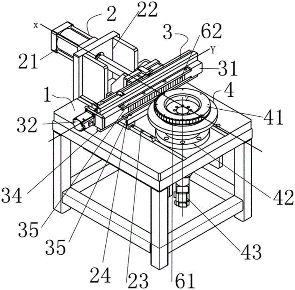
[0039] Embodiment one: as Figure 1-Figure 4The shown equipment for printing on draft beer kegs includes a workbench 1 and a hydraulic pusher 2 installed on the workbench 1, a printing device 3 outside the keg and a printing device 4 inside the keg; the hydraulic pusher 2 Including a hydraulic cylinder 21, a hydraulic cylinder mounting frame 22, a first guide rail 23 and a moving frame 24; the hydraulic cylinder 21 is installed on the workbench 1 through the hydraulic cylinder mounting frame 22, and the first guide rail 23 is laid on the On the table, the moving frame 24 is installed on the first guide rail 23 . The printing device 3 outside the wine barrel includes a connecting frame 31, a Y-axis servo motor 32, a screw 33 and a second guide rail 34; And the Y-axis servo motor 32 drives the screw rod 33 to rotate. One end of the connecting frame is installed on the second guide rail to slide and connect along the Y-axis, and one end is connected to the screw rod in a spiral ...

Embodiment 2

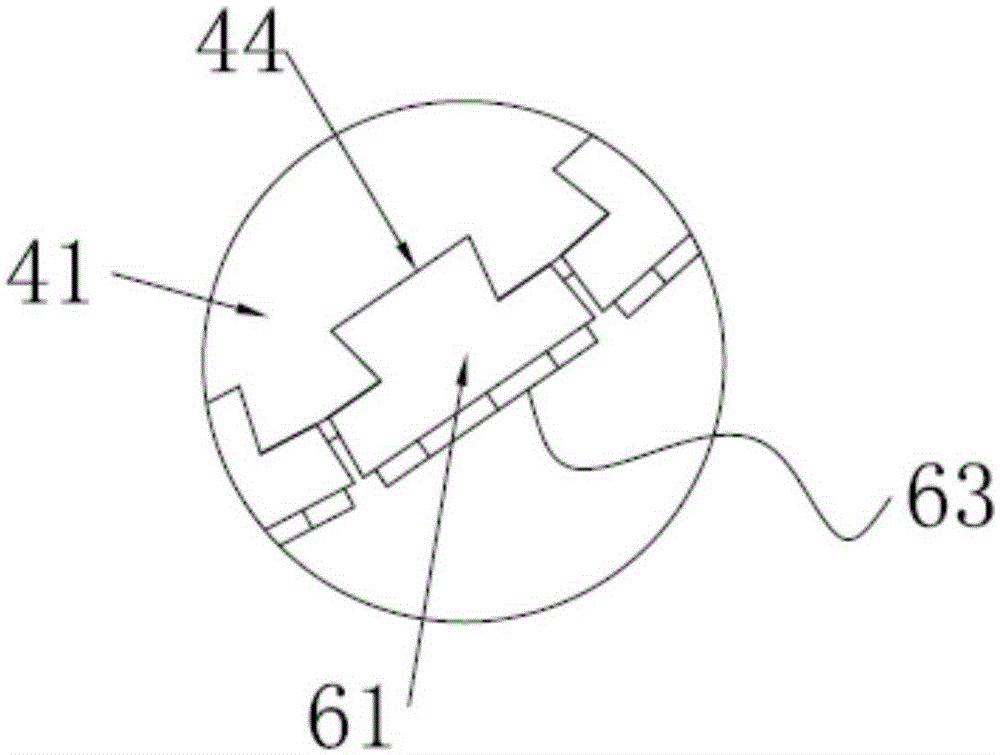
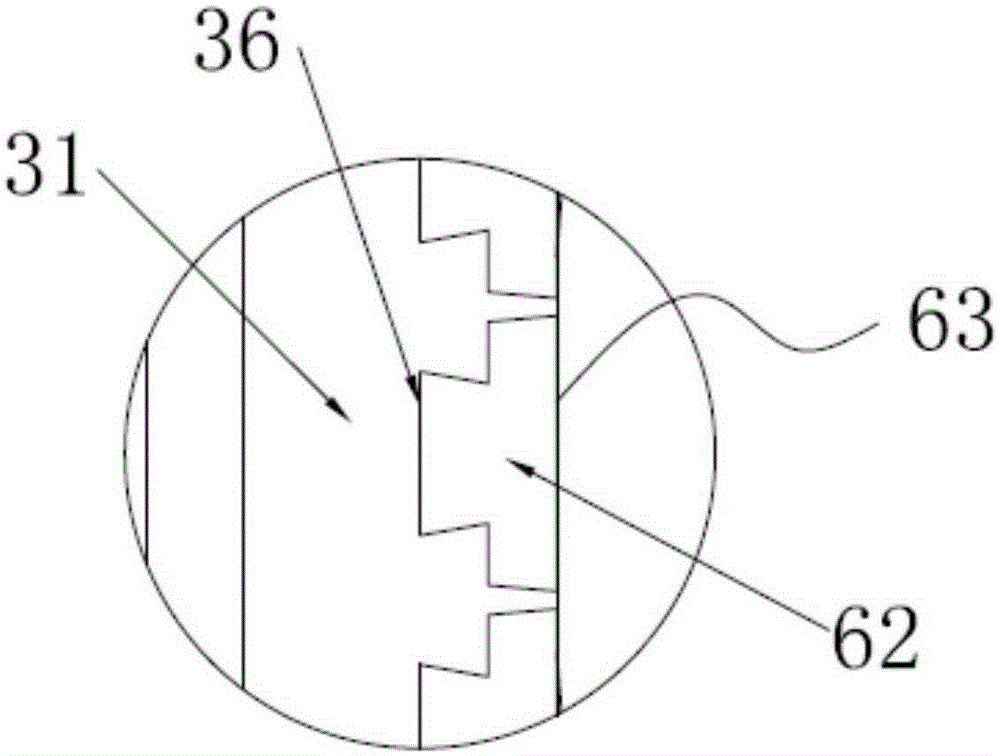
[0041] Embodiment two: if Figure 3-Figure 6 As shown, the inner mold 61 and the outer mold 62 are all designed to include at least one font 63, and the font 63 in the single inner mold 61 is paired with the font 63 in the single outer mold 62 to form a pair of embossed single characters. Font assembly; the circumferential surface of the turntable seat 41 and the Y-axis surface of the connecting frame 31 are all provided with one or more dovetail grooves 44,36, and when there are multiple dovetail grooves 44,36, the dovetail grooves 44,36 The size is the same, and the size of each font 63 is the same. The back of the font 63 is snapped into the dovetail groove 44 so that the font 63 is installed on the Y-axis surface of the connecting frame 31 and the circumferential surface of the turntable seat 41 respectively. Assuming that the logo we need to print is "ABCD", and the design of the inner mold 61 and outer mold 62 of the traditional printing mold is a conjoined font 63 with ...


PUM


Abstract

The invention discloses a device and technology for printing words on a draft bear barrel. The device comprises a workbench, a hydraulic pushing device, a barrel outer-side word printing device and a barrel inner-side word printing device, wherein the hydraulic pushing device, the barrel outer-side word printing device and the barrel inner-side word printing device are installed on the workbench. The barrel inner-side word printing device comprises a rotating disc base rotating by using a Z axis as the axis line. A barrel can be installed on the rotating disc base. An inner mold for printing words on the inner side face of the barrel is installed on the circumferential face of the rotating disc base. The barrel outer-side word printing device comprises a connecting frame moving linearly in the Y-axis direction. An outer mold for printing words on the outer side face of the barrel is arranged on the connecting frame. The hydraulic pushing device controls the outer mold on the connecting frame to move linearly in the X-axis direction, so that the outer mold and the inner mold are matched for imprinting on the side walls of the barrel. According to the device and technology for printing the words on the draft bear barrel, the defect that previous word printing procedures are useless correspondingly due to the fact that stretched and welded semi-finished products are scrapped is avoided, so that the product manufacturing cost is reduced, and the product manufacturing time is shortened.

Description

technical field [0001] The invention belongs to the technical field of engraving, and in particular relates to equipment and technology for printing on draft beer kegs. Background technique [0002] Beer barrels are commonly used containers for beer. In order to ensure the strength of beer barrels, reduce weight and remove rust, beer barrels are usually made of stainless steel and other materials. In order to facilitate identification, the relevant identification information is usually printed on the barrel of the beer barrel. In the traditional process, the identification information is usually printed on the raw material (such as a stainless steel plate) through a printing mold, and then the raw material with the identification information printed The cylinder is made by stretching and welding, but this manufacturing process has the following defects: [0003] 1. After the semi-finished product is scrapped due to operational errors during stretching and welding or other r...

Claims


Application Information

Patent Timeline
Patent Type & Authority Patents(China)
IPC IPC(8): B41F17/18B41M1/26B41M1/40
Inventor 罗邦才孟繁东
Owner NINGBO MASTER DRAFT BEER KEG EQUIP CO
Learn More