Clutch cap screwing device of linear pump cap screwing machine

A capping machine, a straight-line technology, is used in the directions of tightly capping containers, packaging, transportation and packaging with caps, which can solve the problems of high labor costs, inconsistent capping tightness, and high labor intensity, and achieve capping. High efficiency, good capping quality, and manpower saving effect

Active Publication Date: 2014-07-23
常州市金坛晨光轻工机械有限公司
View PDF6 Cites 7 Cited by
  • Summary
  • Abstract
  • Description
  • Claims
  • Application Information

AI Technical Summary

Problems solved by technology

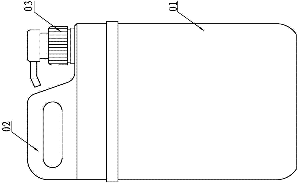
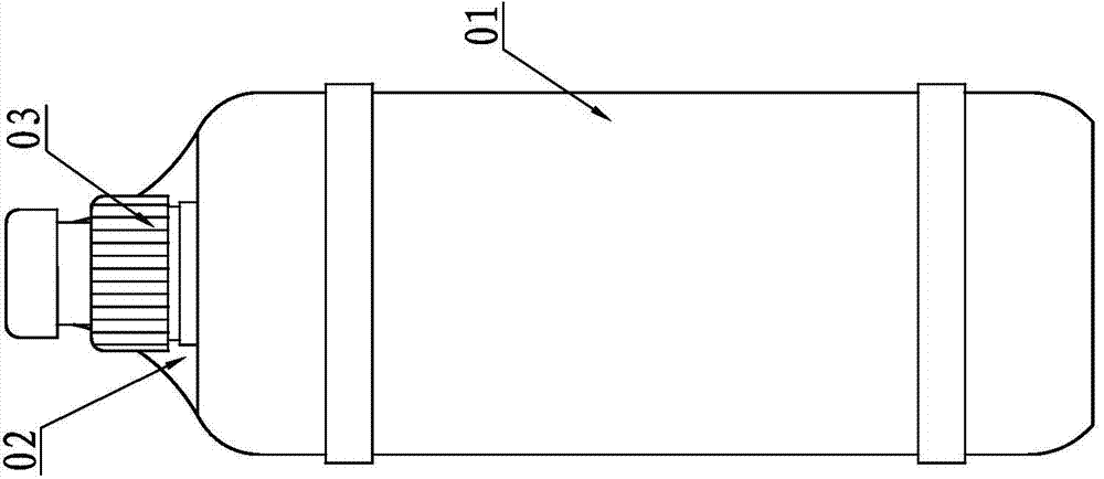
[0002] At present, in daily chemical, food, pharmaceutical and other industries, in order to meet the diversification of people's aesthetics, the setting positions of packaging bottles and caps are different from traditional packaging. Figure 1~2 The packaging bottle shown is one of them. The packaging bottle is composed of a bottle body 01, a handle 02 and a bottle cap 03. The handle 02 and the bottle cap 03 are arranged in a straight line, and the width of the handle 02 is greater than the diameter of the bottle cap 03. The bottle cap 03 It can be either an ordinary bottle cap or a pump cap structure that is very popular now. The demand for this type of packaging bottle is gradually increasing. However, this type of packaging bottle cannot be capped by the existing linear capping machine, and it can be stretched up and down. Shaped vertical capping machines can only cap ordinary bottle caps, and cannot cap caps with pump cap structures. Currently, pump caps can only be capped manually. Workers come to screw caps manually, the efficiency of manual screw caps is very low, and the labor cost is high
Capping workers repeat the boring work of capping all day long. Manual capping is easy to hurt hands. After a day, capping workers are prone to blisters on their hands, sore arms, high labor intensity, unstable capping torque, and variable cap tightness. , the quality of capping cannot be guaranteed, and the liquid leakage after capping is relatively high; at the same time, this manual capping method cannot be matched with the previous high-efficiency linear filling machine

Method used


Image

  • Clutch cap screwing device of linear pump cap screwing machine
  • Clutch cap screwing device of linear pump cap screwing machine
  • Clutch cap screwing device of linear pump cap screwing machine

Examples


Embodiment Construction

[0042] The specific embodiment of the present invention will be further described below in conjunction with the accompanying drawings:

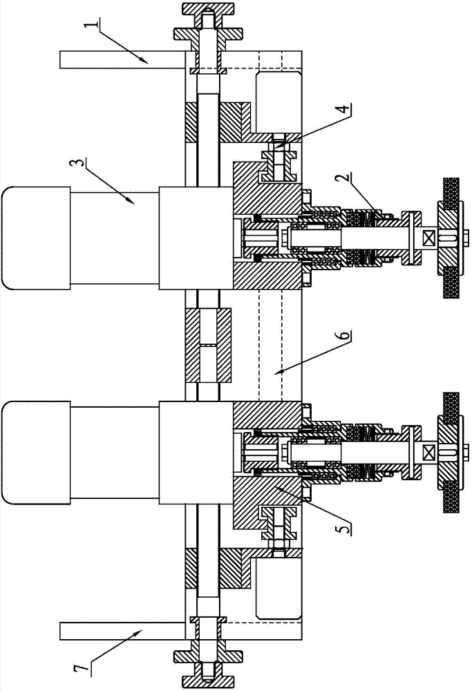
[0043] A clutch capping device of a linear pump capping machine, such as Figure 3 ~ Figure 13 As shown, it includes the front side plate 1 of the rack, the torque cap part 2, the rotary drive part 3, the centering linear drive adjustment mechanism 4, the sliding seat 5, the sliding guide rail 6 and the rear side plate 7 of the rack, and two sliding guide rails 6 It is horizontally and parallelly fixedly installed on the frame front side plate 1 and the frame rear side plate 7, and two guide holes 51 parallel to the upper and lower end faces are provided on the left and right sides of the sliding seat 5, and on the upper and lower end faces of the sliding seat 5 There is a connection through hole 52 on the top, the connection through hole 52 is located on the center line of the axis of the two guide holes 51, the axis of the connection throug...


PUM


Abstract

A clutch cap screwing device of a linear pump cap screwing machine comprises a rack front side plate, torque cap screwing components, rotating driving components, a centering linear driving adjusting mechanism, sliding seats, sliding guide rails and a rack rear side plate. The two sliding guide rails are horizontally and fixedly mounted on the rack front side plate and the rack rear side plate in parallel, the two sliding seats are mounted on the two sliding guide rails in a sleeved mode, the torque cap screwing components are mounted on the lower end faces of the sliding seats, the rotating driving components are mounted on the upper end faces of the sliding seats, the rotating driving components drive the torque cap screwing components, the centering linear driving adjusting mechanism is arranged between the rack front side plate and the rack rear side plate, and a driving motor of the centering linear driving adjusting mechanism is connected with the sliding seats. The clutch cap screwing device of the linear pump cap screwing machine solves the problem of manual cap screwing, a flow process of continuous linear cap screwing can be achieved, a great amount of man power is saved, cap screwing efficiency is high and is 100 times that of manual cap screwing, and the aesthetic standards of people for diversified bottle bodies are met.

Description

Technical field: [0001] The invention relates to a linear packaging capping machine, in particular to a capping device of the capping machine. Background technique: [0002] At present, in daily chemical, food, pharmaceutical and other industries, in order to meet the diversification of people's aesthetics, the setting positions of packaging bottles and caps are different from traditional packaging. Figure 1~2 The packaging bottle shown is one of them. The packaging bottle is composed of a bottle body 01, a handle 02 and a bottle cap 03. The handle 02 and the bottle cap 03 are arranged in a straight line, and the width of the handle 02 is greater than the diameter of the bottle cap 03. The bottle cap 03 It can be either an ordinary bottle cap or a pump cap structure that is very popular now. The demand for this type of packaging bottle is gradually increasing. However, this type of packaging bottle cannot be capped by the existing linear capping machine, and it can be stretc...

Claims


Application Information

Patent Timeline
Patent Type & Authority Applications(China)
IPC IPC(8): B67B3/00
Inventor 眭小平李卫庆
Owner 常州市金坛晨光轻工机械有限公司
Why Eureka
Try Eureka