Multi-core optical fiber manufacturing method

A manufacturing method and technology for multi-core optical fibers, applied in manufacturing tools, glass manufacturing equipment, etc., can solve the problems of increased splicing loss and the inability to precisely fix the core rod, achieve accurate relative positions, reduce the probability of bubbles and bright spots, The effect of saving cladding material

Active Publication Date: 2014-07-23
TIANJIN XINMAO SCI & TECH
View PDF11 Cites 21 Cited by
  • Summary
  • Abstract
  • Description
  • Claims
  • Application Information

AI Technical Summary

Problems solved by technology

The disadvantage of this method is that the relative position of the core rod in the sleeve cannot be fixed accuratel

Method used


Image

  • Multi-core optical fiber manufacturing method
  • Multi-core optical fiber manufacturing method
  • Multi-core optical fiber manufacturing method

Examples


Embodiment 1

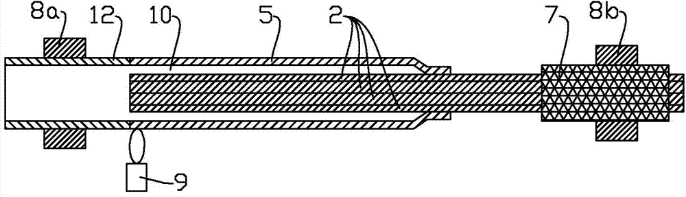
[0027]The mandrel 2 is produced by the VAD process, the refractive index difference Δ is 0.35%, the ratio b / a of the diameter of the cladding layer 4 to the diameter of the core layer 3 is 4.0, its outer diameter is 8 mm after stretching, and it is cut into lengths of 7 mandrels of 1000mm. The seven mandrels 2 are fixed on the clamp 7 after pickling and flame polishing, and the clamp 7 is further installed on the chuck 8b. Then the bushing 5 (with a specification of Φ32mm*2.5mm*800mm) that has been pickled and flame polished is installed on another chuck 8a of the lathe. Next, the plurality of mandrels 2 are slowly moved toward the chuck 8 a, so that the mandrels 2 are inserted into the sleeve 5 , and the ends of the mandrels 2 extend to the interface between the sleeve 5 and the transition sleeve 12 . Rotate the synchronized chucks 8a and 8b at 30 rpm. Move the torch 9 to the end of the sleeve 5 near the clamping end of the mandrel 2 to heat, and the temperature is controll...

Embodiment 2

[0030] Mandrel 2 is produced by MCVD+solution immersion process, and the core layer 3 components are SiO2-Al2O3-Er2O3. The core rod 2 has a refractive index difference Δ of 0.32%, an outer diameter of 5 mm, and a length of 700 mm. The 19 mandrels 2 are fixed on the clamp 7 after pickling and flame polishing, and the clamp 7 is further installed on the chuck 8b. Then the bushing 5 (with a specification of Φ32mm*2.5mm*500mm) that has been pickled and flame polished is installed on another chuck 8a of the lathe. Next, according to the method of Example 1, the assembly of the mandrel and the casing and the online wire drawing are completed. After the optical fiber preform of this embodiment is drawn into the optical fiber 15, the cross-sectional view of the bare optical fiber 1'' with the coating layer stripped is shown in Figure 8 As shown, the optical fiber cladding contains 19 core layers 3''.


PUM


Abstract

The invention discloses a multi-core optical fiber manufacturing method, and belongs to an optical fiber manufacturing method. In the prior art, the relative position of a core rod in a casing pipe cannot be accurately fixed, the fusion splicing loss is increased for the reason of the fiber core position deviation after a multi-core optical fiber is prepared by drawing. According to the method, at least two core rods are fixed to a fixture, the fixture is installed onto a chuck of a lathe; a transition casing pipe with a sleeve is arranged on the other chuck of the same lathe; a core rod is inserted into the sleeve; the chucks are rotated for synchronization, an end part near to a clamping end of the core rod is heated, so that the end part is collapsed onto the core rod; then an interface position of the sleeve and the transition sleeve is heated, and tapering treatment of the sleeve and the core rod is performed, so that one end of the sleeve is sealed; the assembled core rod and the sleeve are respectively welded with an auxiliary quartz rod and a transition quartz sleeve after, then are installed onto a wire-drawer-tower for online vacuum wire drawing to obtain the multi-core optical fiber. In the assembly process of the core rods and the sleeve, a fixture is used for fixing the core rods, so that the relative position of the core rods is more accurate to ensure that the prepared multi-core optical fiber has accurate geometric dimension.

Description

technical field [0001] The invention relates to a method for manufacturing an optical fiber preform rod and an optical fiber, in particular to a method for manufacturing a multi-core optical fiber. Background technique [0002] With the rapid popularization of the Internet and the rapid development of Broadband Integrated Services Digital Network (B-ISDN), the transmission capacity of single-core optical fiber has become a bottleneck. To further expand the transmission capacity, it is necessary to consider converting single-core optical fiber into multi-core optical fiber. [0003] A common optical fiber is composed of a core and a cladding surrounding it, while a multi-core optical fiber contains multiple cores in the same cladding. Therefore, each core in a multi-core fiber is an optical waveguide, that is, one multi-core fiber is equivalent to multiple single-core fibers. Multi-core optical fiber can not only save the manufacturing cost of optical fiber cable, but also g...

Claims


Application Information

Patent Timeline
IPC IPC(8): C03B37/027
Inventor 冯高锋葛锡良杨军勇章海峰董瑞洪马静
Owner TIANJIN XINMAO SCI & TECH
Why Eureka
Try Eureka