
Coking-resistant biomass combustor

A biomass and burner technology, applied in the direction of combustion methods, controlled combustion, and combustion equipment, can solve the problems of narrow fuel application range, equipment fly ash, and endangering the safety of combustion equipment, so as to expand the fuel application range and realize automatic control , the effect of reducing labor intensity

Inactive Publication Date: 2014-07-23
天津市双鑫锅炉辅机有限公司
View PDF7 Cites 2 Cited by
  • Summary
  • Abstract
  • Description
  • Claims
  • Application Information

AI Technical Summary

Problems solved by technology

There are still few researches on biomass burning equipment in our country, and it has not yet reached large-scale application. The main reason is that there are many problems in domestic biomass burning machines, which are mainly reflected in the following two aspects: On the one hand, the fuel adaptability of biomass burning machines Narrow, only suitable for wood pellets, when straw pellets are used, problems such as coking, alkali metal and chlorine corrosion, and serious fly ash in the equipment are prone to occur. The coking problem not only affects the thermal performance of the combustion equipment, but even endangers the safety of the combustion equipment. In view of the serious problem of coking in existing biomass burners, how to optimize the structure of key components of the equipment, reduce the degree of coking, and improve fuel adaptability is the biggest problem facing biomass burners at present; on the other hand, the current biomass burning Machine products are complex in structure and expensive, which is not conducive to large-scale promotion

Method used


Image

  • Coking-resistant biomass combustor
  • Coking-resistant biomass combustor

Examples


Embodiment Construction

[0022] In order to make the technical problems, technical solutions and beneficial effects solved by the present invention clearer, the present invention will be further described below in conjunction with the accompanying drawings and embodiments. It should be understood that the embodiments described here are only used to explain the present invention, not to limit the present invention.

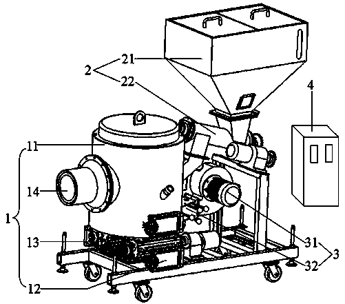
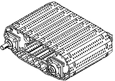
[0023] Such as figure 1 As shown, an anti-coking biomass burner includes a combustion furnace (1), a feeding system (2), an air supply system (3) and an intelligent control system (4), and a combustion chamber ( 11), settling chamber (12) and chain grate (13), the settling chamber (12) is set under the combustion chamber (11), and the chain grate (13) is set in the combustion chamber ( 11) and the settling chamber (12), the chain grate (13) is driven by a motor to move at a constant speed, and a burner (14) is provided on one side of the combustion furnace (1), and the combustion furnace ...


PUM


Abstract

The invention provides a coking-resistant biomass combustor. The coking-resistant biomass combustor comprises a combustion furnace, a feeding system, an air supply system and an intelligent control system. A combustion chamber, a setting chamber and a chain grate stoker are arranged in the combustion furnace. The chain grate stoker is arranged between the combustion chamber and the setting chamber and is driven by the motor to conduct uniform motion. A nozzle is arranged on one side of the combustion chamber and the other side of the combustion chamber is connected with the feeding system. The feeding system comprises a hopper and a spiral feeding machine. The air supply system comprises a fan and air ducts used for air supply. The air ducts comprise the first air duct, the second air duct and the third air duct. The biomass combustor is provided with the chain grate stoker. Biomass fuel is combusted on the chain grate stoker so that under the condition that generated coke is not cooled, the coke can also fall into the setting chamber along with the uniform motion of the chain grate stoker and the potential safety hazard that coking on the chain grate stoker is generated can be eliminated. Meanwhile, three-time air supply is adopted, so that the fuel is combusted more thoroughly and the combustion efficiency is improved.

Description

technical field [0001] The invention belongs to the field of combustion equipment, and relates to a biomass burner, in particular to an anti-coking biomass burner. Background technique [0002] Biomass burner is a kind of biomass semi-gasification automatic control burner, and it is a biomass pyrolysis burner that uses biomass particles as fuel. Biomass fuel engine has the advantages of high thermal efficiency and low smoke exhaust pollution. Its application in foreign countries began in the 1980s, and countries such as Sweden, Denmark, Austria and Germany have certain applications. There are still few researches on biomass burning equipment in our country, and it has not yet reached large-scale application. The main reason is that there are many problems in domestic biomass burning machines, which are mainly reflected in the following two aspects: On the one hand, the fuel adaptability of biomass burning machines Narrow, only suitable for wood pellets, when straw pellets a...

Claims


Application Information

Patent Timeline
Patent Type & Authority Applications(China)
IPC IPC(8): F23B30/08F23H11/00F23L9/00F23N1/02
Inventor 潘月双
Owner 天津市双鑫锅炉辅机有限公司
Learn More