
Welding gun cleaning device and welding wire cutting device

A welding wire cutting and welding torch cleaning technology, which is applied to cleaning welding torches and welding accessories, can solve the problems of false alarms from welding robot anti-collision sensors, time-consuming and labor-intensive disassembly and installation, and inconvenient use. It achieves a wide range of applications and quick disassembly and installation , to achieve the effect of flexibility

Active Publication Date: 2014-07-30
TBI SHANDONG IND
View PDF6 Cites 4 Cited by
  • Summary
  • Abstract
  • Description
  • Claims
  • Application Information

AI Technical Summary

Problems solved by technology

[0006] Insufficiency of the mechanical touch method: because most welding robots are equipped with anti-collision sensors at present, for welding robots equipped with high-sensitivity anti-collision sensors, when the mechanical switch in the welding wire cutting device is activated, the contact force requirements When the size is large, it is easy to cause a false alarm by the anti-collision sensor of the welding robot, causing the entire welding system to stop
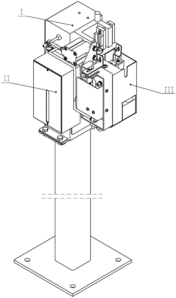
Its disadvantage is that during use, the anti-splash agent cover 9 is fixed on the main body of the anti-splash agent bottle bracket II and the gun cleaning device bracket I
The disassembly and installation process is time-consuming and labor-intensive, and the position of the anti-splash agent nozzle IV needs to be re-adjusted after re-installation, which brings a lot of inconvenience to the use and restricts the rhythm and efficiency of automated production

Method used


Image

  • Welding gun cleaning device and welding wire cutting device
  • Welding gun cleaning device and welding wire cutting device
  • Welding gun cleaning device and welding wire cutting device

Examples


Embodiment Construction

[0077] In order to facilitate the understanding of the technical solution of the present invention, the technical content involved in it will be further described below in conjunction with the accompanying drawings.

[0078] In describing the present invention, it should be noted that the orientation or position indicated by the terms "left", "right", "front", "rear", "upper", "lower", "inner", "outer" etc. The relationship is based on the orientation or positional relationship shown in the drawings, and is only for the convenience of describing the present invention and simplifying the description, rather than indicating or implying that the referred device or element must have a specific orientation, be constructed and operated in a specific orientation, therefore It should not be construed as a limitation of the present invention.

[0079] In the description of the present invention, it should be noted that unless otherwise specified and limited, the terms "installation", "...


PUM


Abstract

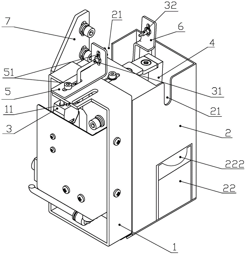
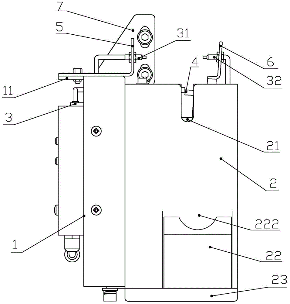
The invention provides a welding gun cleaning device and a welding wire cutting device. The welding wire cutting device comprises a rack, a wire cutting machine cover, a through beam type photo electric sensor, a wire cutting machine, a left support arm, a right support arm and a waste collecting box, wherein a concave arm which extends towards left is arranged on the upper end surface of the rack, a strip-shaped through groove is formed in the concave arm, the rack is connected with the wire cutting machine cover, the through beam type photo electric sensor main body and an electromagnetic valve of the wire cutting machine are fixed inside the rack, the left support arm is L-shaped, the strip-shaped through grooves are formed in both the left support arm and the right support arm, the left support arm is fixed on the upper end surface of the concave arm, a light emitter is fixed on the left support arm, the right support arm is fixed on the wire cutting machine cover, and a light receiver is fixed on the right support arm. The device can collect the cut waste, uses the photo electric sensing control way to control the cutting operation, and avoids the phenomenon of error alarm caused by that a welding robot collides; the device can be directly used for the welding robot which is few in output signal, the positions of the light emitter and the light receiver can be adjusted, and the device can be suitable for the arms of the welding robots in different appearance sizes.

Description

technical field [0001] The invention relates to peripheral equipment of a welding robot and belongs to the technical field of welding torch cleaning devices. Background technique [0002] In the complete welding robot system, in addition to the robot itself, it also includes some peripheral equipment, such as positioner, mobile slide, welding torch cleaning device, automatic tool conversion device. To complete the welding operation, the robot needs to rely on the support and cooperation of the control system and peripheral auxiliary equipment, and use them in coordination to reduce forced downtime, reduce equipment failure rate, improve safety, and obtain rational welding quality. [0003] As we all know, robot welding has outstanding features such as high production efficiency and stable welding quality. However, during the construction process of the metal arc welding robot, the residual welding slag inside and outside the welding torch nozzle and the change of the dry el...

Claims


Application Information

Patent Timeline
IPC IPC(8): B23K9/32B21F11/00
CPCB21F11/00B23K9/32B23K9/328
Inventor 严海李涛姜坤白春泽
Owner TBI SHANDONG IND
Learn More