
Six-guide-wheel multi-line cutting machine

A multi-wire cutting machine and guide wheel technology, which is applied to fine working devices, stone processing equipment, manufacturing tools, etc., can solve the problems of increasing the diameter of the cutting wire 5, difficult to ensure product quality, and reducing the machining accuracy of workpieces. The effect of smooth wiring, reducing wiring resistance and prolonging life

Inactive Publication Date: 2014-07-30
唐山晶玉科技股份有限公司
View PDF8 Cites 11 Cited by
  • Summary
  • Abstract
  • Description
  • Claims
  • Application Information

AI Technical Summary

Problems solved by technology

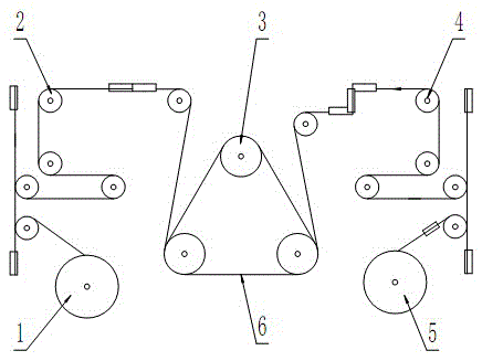
[0003] as attached figure 1 As shown, the existing multi-wire cutting machine generally guides the cutting wire 5 to the sheave 3 in the processing area of ​​the material to be cut through a set of wire-releasing guide wheel assembly 2 for cutting, and then the cutting wire is guided by the wire-receiving guide wheel assembly 4. 5 Guide to the take-up roller assembly to wind and take up the wire. Since the number of guide wheels is an important factor affecting the cutting speed and the diameter of the cutting line 5, the more the number of guide wheels, the greater the resistance of the cutting line 5 and the lower the maximum cutting speed At the same time, the diameter of the cutting line 5 needs to be increased accordingly, which reduces the machining accuracy of the workpiece. Therefore, the existing multi-wire cutting machine has defects such as low production efficiency and difficult product quality assurance.

Method used


Image

  • Six-guide-wheel multi-line cutting machine
  • Six-guide-wheel multi-line cutting machine
  • Six-guide-wheel multi-line cutting machine

Examples


Embodiment Construction

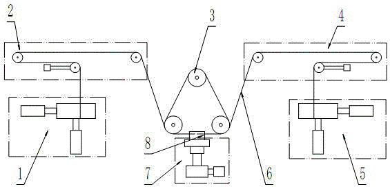
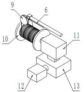
[0016] see figure 2 , the present invention is provided with pay-off roller assembly 1, pay-off guide wheel assembly 2, sheave assembly 3, take-up guide wheel assembly 4, take-up roller assembly 5, cutting line 6 and workbench 7; Said cutting line 6 One end is wound on the pay-off roller assembly 1, which is guided by the pay-off guide wheel assembly 2 and wound on the sheave assembly 3 to form a steel wire mesh, then guided by the take-up guide wheel assembly 4 and wound on the take-up roller assembly 5 Above; the cutting line 6 realizes reciprocating motion under the joint drive of the pay-off roller assembly 1 and the take-up roller assembly 5, the workpiece 8 to be cut is placed on the workbench 7, and the feed of the workpiece 8 is realized by lifting the workbench 7 , which is special in that: the pay-off guide wheel assembly 2 and the take-up guide wheel assembly 4 are symmetrically arranged on the left and right sides of the sheave assembly 3, and are co-located betwe...


PUM


Abstract

The invention provides a six-guide-wheel multi-line cutting machine, which is used for solving the problem that a cutting line of an existing multi-line cutting machine is unsmooth to route. The machine is provided with a pay-off roller component, a pay-off guide wheel component, a grooved wheel component, a take-up guide wheel component, a take-up roller component, a cutting line and a worktable, wherein one end of the cutting line is intertwined on the pay-off roller component; the cutting line is guided and intertwined on the grooved wheel component through the pay-off guide wheel component to form a steel wire net, and then is guided and intertwined on the take-up roller component through the take-up guide wheel component; the cutting line is jointly driven by the pay-off roller component and the take-up roller component to realize reciprocating motion; the multi-line cutting machine realizes the feeding of a workpiece through the lifting of the worktable, and is characterized in that total six guide wheels are arranged in each of the pay-off guide wheel component and the take-up guide wheel component. By applying the six-guide-wheel multi-line cutting machine, not only can the cutting speed be improved, but also the product quality is guaranteed; meanwhile, the service life of the cutting line is also prolonged, and the production cost is lowered.

Description

technical field [0001] The invention relates to a multi-wire cutting machine, in particular to a multi-wire cutting machine which guides cutting wires through six guide wheels, and belongs to the technical field of brittle material processing equipment. Background technique [0002] Multi-wire cutting machine is the key equipment in the core device substrate manufacturing process of IC (Integrated Circuit), IT (Information Technology), PV (Photovoltaic) and other industries. Multi-wire cutting is currently the most advanced slicing processing technology. Its principle is that the cutting wire (steel wire) passes through a set of grooved wheels to form a steel wire mesh with a certain distance, and uses the high-speed reciprocating motion of the cutting wire to bring the abrasive into the processing area of ​​the material to be cut. Grinding, while the workpiece to be cut is fed through the lifting and lowering of the worktable, so as to realize the innovative slicing pro...

Claims


Application Information

Patent Timeline
Patent Type & Authority Applications(China)
IPC IPC(8): B28D5/04
Inventor 杨福占张静波张朝辉
Owner 唐山晶玉科技股份有限公司
Learn More