Direct-looking synthetic aperture laser imaging radar reflective electro-optical scanning device

A technology of synthetic aperture laser and imaging radar, which is applied in the direction of measuring device, utilization of re-radiation, re-radiation of electromagnetic waves, etc., can solve the problems of limited scanning accuracy, large moment of inertia, and large vibration influence, and achieve simple and compact devices and small volume , the effect of flexible control

Active Publication Date: 2016-12-07
SHANGHAI INST OF OPTICS & FINE MECHANICS CHINESE ACAD OF SCI
View PDF2 Cites 0 Cited by
  • Summary
  • Abstract
  • Description
  • Claims
  • Application Information

AI Technical Summary

Problems solved by technology

However, the prior art [1] considers that the relative rotation deflection system is used to scan the two beams against each other and the beams are propagated through space diffraction to obtain the spatial parabolic phase difference of the wavefront of the inner emission light field. The system is bulky, and It is designed based on the relative rotation and deflection of mechanical scanning, and its vibration has a great influence, and the scanning speed scans to the influence of the mechanical moment of inertia, and the speed is slow
[0004] Prior technology [2] (Liu Liren, direct-looking synthetic aperture laser imaging radar separate wave surface conversion scanning device, publication number: CN103344952A) and prior technology [3] (Liu Liren, direct-looking synthetic aperture laser imaging radar emission beam direct wave surface conversion scanning Device, Publication No.: CN103245939A) in the direct-looking synthetic aperture laser imaging radar wave surface conversion launch device, it is still considered to use a cylindrical mirror to directly scan in translation at the inner launch field or to use a reflective galvanometer to scan mechanically, and the scanning accuracy is limited. , Slow response speed, large moment of inertia, which is not conducive to the application on high-speed carrying platforms such as airborne

Method used


Image

  • Direct-looking synthetic aperture laser imaging radar reflective electro-optical scanning device
  • Direct-looking synthetic aperture laser imaging radar reflective electro-optical scanning device
  • Direct-looking synthetic aperture laser imaging radar reflective electro-optical scanning device

Examples


Embodiment Construction

[0017] The present invention will be further described below in conjunction with the accompanying drawings and embodiments, but the protection scope of the present invention should not be limited thereby.

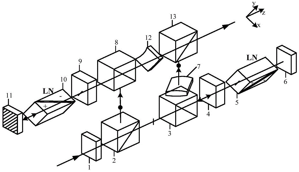
[0018] see first figure 1 , figure 1 It is a structural diagram of the direct-looking synthetic aperture laser imaging radar reflective electro-optical scanning device of the present invention. As can be seen from the figure, the direct-looking synthetic aperture laser imaging radar reflective electro-optic scanning device of the present invention consists of a half-wave plate 1, a first polarizing beam splitter 2, a second polarizing beam splitter 3, a first Faraday rotator 4, a first electro-optic Scanner 5, first mirror 6, first cylindrical mirror 7, third polarizing beam splitter 8, second Faraday rotator 9, second electro-optic scanner 10, second emitting mirror 11, second cylindrical mirror 12 and a fourth polarizing beam splitter 13. The first electro-optic scanne...


PUM


Abstract

A reflection-type electro-optical scanning device of down-looking synthetic aperture laser imaging radar is placed between a laser source and a primary emitting mirror and comprises a half wave plate, a first polarization beam splitter, a second polarization beam splitter, a first Faraday rotator, a first electro-optical scanner, a second reflector, a first cylindrical mirror, a third polarization beam splitter, a second Faraday rotator, a second electro-optical scanner, a second emitting mirror, a second cylindrical mirror and a fourth polarization beam splitter. According to the reflection-type electro-optical scanning device of the down-looking synthetic aperture laser imaging radar, an electro-optical linear scanning range twice as large as that generated through a transmission-type electro-optical scanning device can be generated through the reflection-type electro-optical scanning device, wave surface phase difference distribution of a parabolic equipotential line at the far field target position of two polarization orthogonal beams is finally achieved, the reflection-type electro-optical scanning device is used for scanning a target, the structure is simple, mechanical scanning is avoided, the response speed of the electro-optical phase modulation wave surface is high, the size is small, the weight is low, and the reflection-type electro-optical scanning device is suitable for an emitting system of the down-looking synthetic aperture laser imaging radar on an onboard rapidly-operating carrying platform and the like.

Description

technical field [0001] The invention relates to a laser emission system of a direct-view synthetic aperture laser imaging radar, in particular to a direct-view synthetic aperture laser imaging radar reflective electro-optical crystal scanning device placed between a laser light source and a primary emitting mirror. The device conducts linear electro-optical scanning in the cross-track direction through two-way reflective electro-optic scanners to generate a linear term phase modulation of the cross-track to the lateral position of the target point, and performs phase modulation in the along-track direction through a cylindrical mirror to generate a The quadratic term phase history centered on the longitudinal position of the target point and the finally obtained polarization orthogonal parabolic equipotential phase difference wavefront are the key technologies for realizing radar two-dimensional plane target imaging. Background technique [0002] The principle of synthetic a...

Claims


Application Information

Patent Timeline
Patent Type & Authority Patents(China)
IPC IPC(8): G01S7/481
CPCG01S7/4814G01S17/90
Inventor 卢智勇孙建锋职亚楠周煜许倩刘立人
Owner SHANGHAI INST OF OPTICS & FINE MECHANICS CHINESE ACAD OF SCI
Why Eureka
Try Eureka