Method for minimizing fatigue damage in welded structure, tool for forming strike mark, and welded structure

A fatigue damage and welded structure technology, applied in welding/welding/cutting items, manufacturing tools, welding equipment, etc., can solve problems such as fatigue cracks, and achieve the effect of suppressing fatigue damage

Active Publication Date: 2014-07-30
JFE STEEL CORP
View PDF8 Cites 12 Cited by
  • Summary
  • Abstract
  • Description
  • Claims
  • Application Information

AI Technical Summary

Problems solved by technology

Therefore, according to the method described in Non-Patent Document 1, such as Figure 5 As shown, in the case of performing hammering on the out-of-plane gusset weld joint (out-of-plane gusset weld joint) that makes the rib (rib) 2 stand upright on the surface of the base metal 1, there is a weld in the weld seam 3 The toe 4 forms a deep groove where the stress concentrates, thereby causing the risk of fatigue cracks from the weld toe 4 of the weld 3

Method used


Image

  • Method for minimizing fatigue damage in welded structure, tool for forming strike mark, and welded structure
  • Method for minimizing fatigue damage in welded structure, tool for forming strike mark, and welded structure
  • Method for minimizing fatigue damage in welded structure, tool for forming strike mark, and welded structure

Examples


no. 1 approach 〕

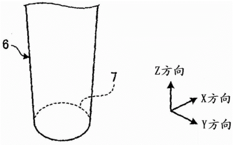
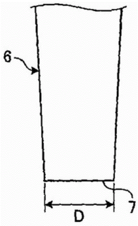
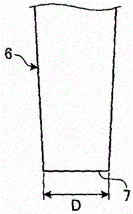
[0057] The tool 6 for forming a blow mark used when implementing the fatigue damage suppression method of a welded structure according to the first embodiment of the present invention is also made of high-strength steel (high-strength steel) (SM570 grade or higher) with a tensile strength of 600 MPa or more at least. ) formed, and as figure 1 as well as Figure 2A ~ Figure 2C As shown, it has a blow mark forming surface 7 at the front end. The impact mark forming surface 7 is used to form a substantially linear and curved weld seam 3 (refer to Figure 5 ) the surface where the strike mark 5 is formed on the surface of the adjacent base material 1 . Such as Figure 2A ~ Figure 2C As shown, the scratch formation surface 7 is flat and circular with a radius of not less than 1.5 mm and not more than 3.0 mm, that is, a diameter D of not less than 3.0 mm and not more than 6.0 mm. As the definition of "circle" of the impact mark forming surface 7 formed in a circle, the ratio of ...

Embodiment 1

[0070] The present inventors under the welding conditions (welding condition) that the welding current (welding current) is 280A, the welding voltage (welding voltage) is 32V, and the welding speed (welding speed) is 28cpm, the Figure 6A , Figure 6B The welded joints shown were prepared as test pieces, and a compressive residual stress introduction test was performed under the conditions shown in Table 1 using the prepared welded joints.

[0071] 〔Table 1〕

[0072] [Table 1]

[0073]

[0074] * Residual stress at weld toe: Measurement result of residual stress using X-ray

[0075] Examples 1 to 4 in Table 1 show the following cases: on the surface of the base material 1 adjacent to the weld 3, using the tool 6 for forming a dent with the diameter D of the dent forming surface 7 being 3mm, 4mm, 5mm, or 6mm, Striking marks 5 having a maximum depth of 0.03 mm or more and less than 0.50 mm are continuously formed along the weld seam 3 . Examples 5 to 8 in Table 1 show the...

Embodiment 2

[0081] The present inventors used tools for forming blow marks having the tip shapes shown in Table 2 (Examples 11 to 18 and Comparative Examples 11 to 16), and hammered (air pressure : about 0.588MPa (about 6kg / cm 2 ), frequency: 90Hz, moving speed: 0.25mm / sec), vertically strike marks along the welding line throughout the length of 100mm and strike repeatedly with tools so that the distance from the weld toe of the weld to the base metal side is 5mm The maximum depth of the strike mark in the area is 0.02-0.50 mm, and then, the residual stress at a position 1 mm away from one end of the strike mark 5 (the end on the side of the welding toe 4 ) is measured by X-ray. Take the beam diameter as Measurement of residual stress using X-rays is performed. Table 2 shows the test results.

[0082] 〔Table 2〕

[0083] [Table 2]

[0084]

[0085] * Residual stress at weld toe: Measurement result of residual stress using X-ray

[0086] Examples 11 to 14 in Table 2 show the follo...


PUM

PropertyMeasurementUnit
radiusaaaaaaaaaa
lengthaaaaaaaaaa
lengthaaaaaaaaaa

Abstract

A method for minimizing fatigue damage in a welded structure by minimizing the fatigue damage produced in the welded portion of the welded structure. In this method, a substantially linear weld bead is curved in an arc-shape along a direction that transverses the weld bead at a right angle on the surface of a base material adjacent to the bead in the welded portion, and a strike mark is formed through hammer peening or ultrasonic shock peening using a tool for forming a strike mark having at the tip a strike-mark-forming surface with the center of curvature skewed to one side of two end surfaces mutually parallel along the weld bead; a strike mark is formed on the surface of the base material adjacent to the substantially linear and curved weld bead through hammer peening or ultrasonic shock peening using a tool for forming a strike mark having at the tip a planar strike-mark-forming surface with an overall circular or elliptical shape; and fatigue damage on the welded portion is minimized by introducing compressive residual stress in the vicinity of a weld bead toe with the tool for forming a strike mark.

Description

technical field [0001] The present invention relates to a fatigue damage suppression method (Method for preventing fatigue damage) of welded structures (welded structures) (also called steel structures (steel structures)) that suppresses fatigue damage (fatigue damage) in welded parts, Tools for forming impact area, and welded structures. Background technique [0002] In recent years, reports of damage cases of steel bridges due to corrosion and fatigue have increased as steel bridges age. In order to suppress damage to steel bridges, it is first necessary to establish an inspection system. However, especially in the case of fatigue damage, it is important to reduce working external force from passing vehicles or the like, or to improve weld quality from the design-manufactured side. In welded structures such as steel bridges, there are cases where a weld toe is stressed due to defects such as cracks in the weld zone or improper shape of the weld bead. Concentration (stre...

Claims


Application Information

Patent Timeline
Patent Type & Authority Applications(China)
IPC IPC(8): B23K31/00
CPCC21D7/06B23K31/02B23K31/125B23K2103/04C21D9/50
Inventor 森影康伊木聪
Owner JFE STEEL CORP
Why Eureka
Try Eureka