
Gas filtration device

A filter device and gas technology, applied in the direction of dispersed particle filtration, dispersed particle separation, chemical instruments and methods, etc., can solve the problems of low filter accuracy, dew condensation on the surface of the filter element, blockage of fine particles of the filter element, etc.

Active Publication Date: 2014-08-06
CHENGDU INTERMENT TECH
View PDF6 Cites 6 Cited by
  • Summary
  • Abstract
  • Description
  • Claims
  • Application Information

AI Technical Summary

Problems solved by technology

The common features of the technical solutions adopted in the above-mentioned CN101721848A and CN102350121A are: the voltage is applied between the filter element and the shell, no closed loop is formed, and no continuous current is generated on the filter element
[0004] On the other hand, in the field of gas filtration, especially in the field of high-temperature gas filtration, the following problems are often faced: first, the filter element is easily blocked by fine particles; , Back blowing air at room temperature and contact with the filter element during back blowing and soot cleaning, etc.) It is easy to cause condensation on the surface of the filter element, forming a paste or hardened substance, which rapidly reduces the filtration efficiency of the filter element
Regarding the first problem, the current mainstream view is that the filtration accuracy of the filter element is not high, which causes the fine particles in the gas to be filtered to drill into the pores of the filter element to block the pores. Therefore, it is generally advocated to overcome it by improving the filtration accuracy of the filter element, but Practice has proved that the effect is not ideal; for the second problem, the current method is to heat the back blowing gas and then act on the filter element through the back blowing soot cleaning device.

Method used


Image

  • Gas filtration device

Examples


Embodiment

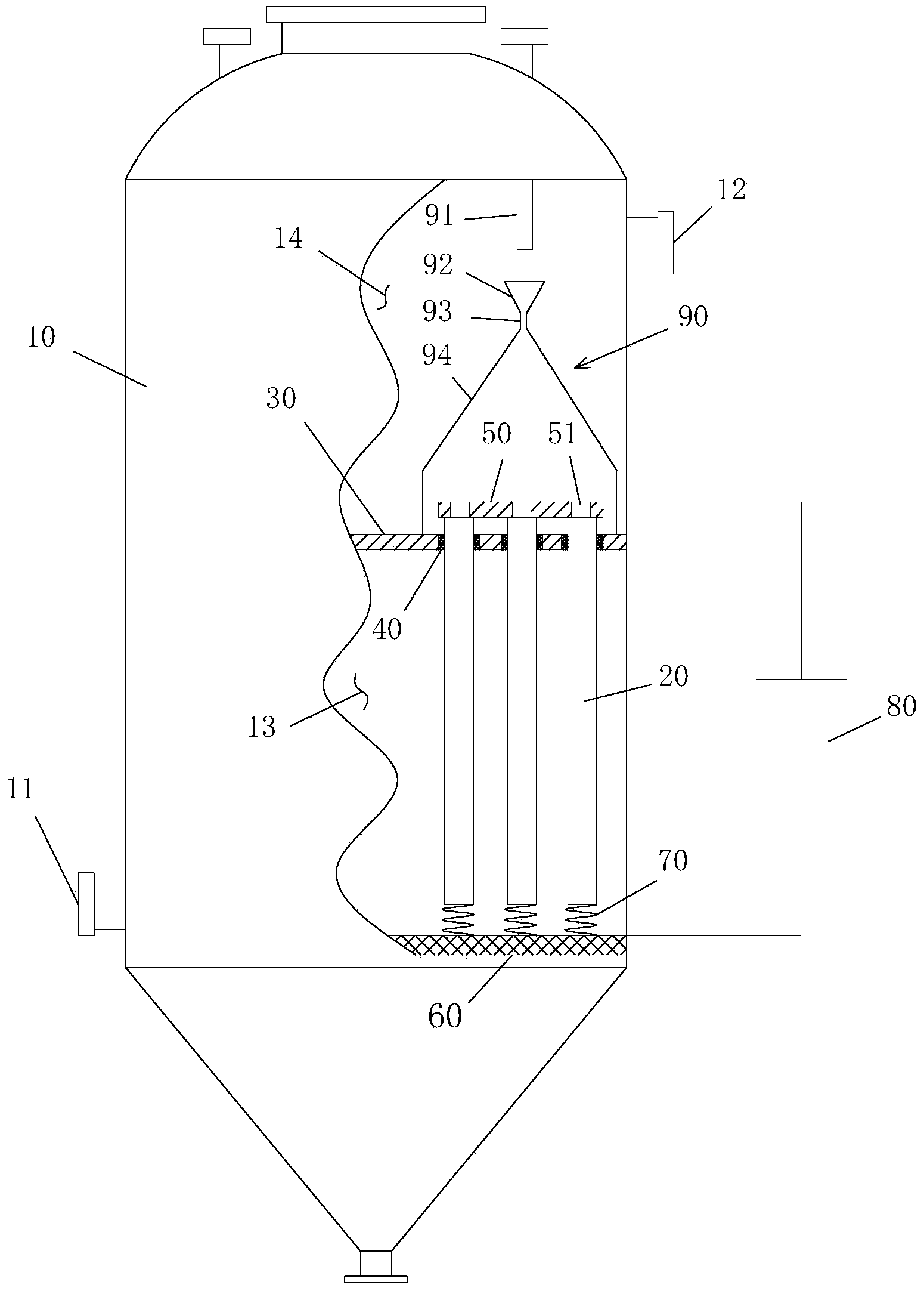
[0016] Adopt said gas filtering device in the above-mentioned specific embodiment, wherein used filter element 20 is the filter element that a kind of Fe-Al base alloy porous material is made, and the alloy composition of this material is: Fe accounts for 67% (weight); Al 20% by weight; Si 5% by weight; Ni 5% by weight and Mo 3% by weight. The material is prepared by powder metallurgy. The preparation method mainly includes three steps: material preparation, molding and sintering. The specific process is basically the same as the current process for preparing sintered porous materials by powder metallurgy. After heat preservation at 1300° C. for 2 hours, cooling is carried out to finally obtain the filter element 20 product. The resistance of the filter element is about 45Ω. Use the above-mentioned filter element 20 gas filter device to process the lead anode slime smelting furnace gas at a temperature of 400-500°C (Note: lead anode slime is a by-product produced in the proce...


PUM

PropertyMeasurementUnit
Resistanceaaaaaaaaaa

Abstract

The invention discloses a gas filtration device, which can facilitate gas filtration through heating gas entering the device. The gas filtration device comprises a casing and a filter element which is mounted inside the casing and is a conductor, wherein the casing is connected with the filter element in an insulated manner to form a first space and a second space which are separated from each other; the gas to be filtered is conveyed to the first space, the gas after filtration is conveyed to the second space; a positive pole connecting end and a negative pole connecting end are arranged on the filter element; during filtration, the positive pole connecting end and the negative pole connecting end are connected with a positive pole and a negative pole of a power supply respectively to form a closed circuit so as to enable the filter element to form a filtration component serving as an electric heating body; the heating power of the electric heating body can enable the temperature of the gas at the gas inlet lower than or equal to the temperature of the gas at the gas outlet; even the gas to be filtered contains substances which is condensed due to a low temperature, the holes of the filter element are not blocked by the precipitation of the substances during the filtration.

Description

technical field [0001] The invention relates to a gas purification device, in particular to a gas filter device. Background technique [0002] The structure of the gas filter device used in industry generally includes a shell, a filter element installed in the shell, and a back-blowing dust cleaning device acting on the filter element. The shell is connected with the filter element to form a separated first space and a second space, to be filtered The transmission of the gas occurs in the first space, and the transmission of the filtered gas occurs in the second space. The casing is respectively provided with an inlet port of the gas to be filtered communicating with the first space and an exhaust of the filtered gas communicating with the second space. mouth. At present, the filter element is mainly a non-conductive cloth bag or a ceramic filter element. The applicant of the present invention is committed to developing intermetallic compound porous material filter cores, ...

Claims


Application Information

Patent Timeline
IPC IPC(8): B01D46/00B01D46/42
Inventor 高麟汪涛郑其灵
Owner CHENGDU INTERMENT TECH
Learn More