Slurry bed reactor
A reactor and slurry bed technology, which is applied in the field of high-efficiency internal circulation slurry bed reactors, can solve problems such as affecting reaction efficiency, backmixing, and large gas and slurry sliding speed.
- Summary
- Abstract
- Description
- Claims
- Application Information
AI Technical Summary
Problems solved by technology
Method used
Image
Examples
Embodiment 1
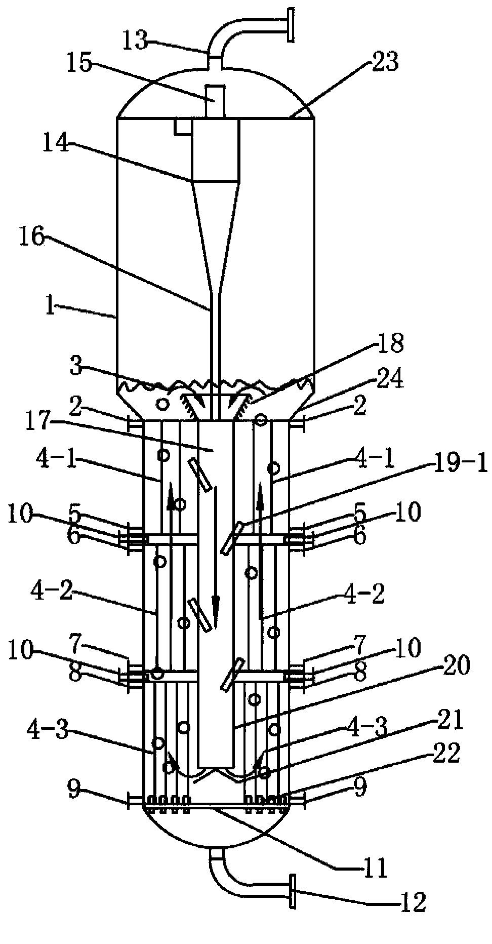
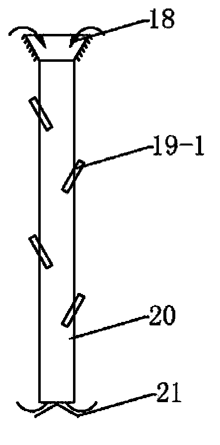
[0084] This example uses figure 1 The reactor shown is for Fischer-Tropsch synthesis. The inner diameter of the slurry bed stainless steel reactor shell is 1.2 meters, and the axial height of the reactor is 35 meters. liquid separator. The liquid level of the slurry bed is located 18 meters above the syngas distributor. The upper edge of the expansion port at the top of the draft tube is located at a height of 14.5 meters above the syngas distributor, the bottom of the feeding tube of the draft tube is located at a height of 0.2 meters above the syngas distribution plate, and the inner diameter of the feeding tube 20 of the draft tube 17 is 0.36 m. rice.
[0085] The draft tube is completely submerged below the liquid level of the slurry bed, and the outer surface of the expansion port at the upper end of the draft tube 17 includes six rows of ring-shaped raised structures. The height of these ring-shaped raised structures is 0.25 meters, and the included angle with the axia...
Embodiment 2
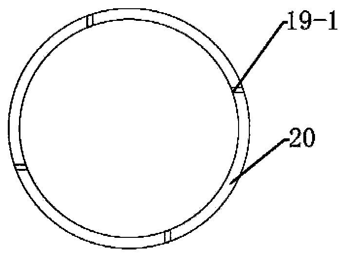
[0091] Embodiment 2: use the same reaction device as in Example 1, but the difference is that, as shown in Figure 8 (b), the following changes have been made to the arrangement of the nozzles in the draft tube: 8 nozzles are divided into two layers and arranged , the vertical distance between the two layers is 4 meters, and each layer is provided with 4 nozzles, which are installed at 4 meters and 8 meters below the expansion section of the diversion pipe. These nozzles are evenly arranged around the circumference of the diversion pipe, and each nozzle The included angle between directions is 30°, and the arrangement of nozzles in the horizontal direction is still as shown in Figure 8(c), that is, the nozzle opening direction is along the tangential direction of the duct wall. The relevant experimental results are shown in Table 2.
Embodiment 3
[0092] Embodiment 3: The reactor setting method is the same as that of Example 1, the difference is that, in the top view, the nozzle is set in the manner shown in Figure 8(d), so that the opening of the nozzle is closer to the position in the middle of the draft tube, and the opening direction The angle between the nozzle and the tangential direction where the nozzle passes through the wall of the draft tube is about 60 degrees. This arrangement can prevent the jet from being hindered by the wall of the reactor. The relevant experimental results are shown in Table 2.
PUM
| Property | Measurement | Unit |
|---|---|---|
| quality score | aaaaa | aaaaa |
Abstract
Description
Claims
Application Information
 - R&D
- Intellectual Property
- Life Sciences
- Materials
- Tech Scout
- Unparalleled Data Quality
- Higher Quality Content
- 60% Fewer Hallucinations
Browse by: Latest US Patents, China's latest patents, Technical Efficacy Thesaurus, Application Domain, Technology Topic, Popular Technical Reports.
© 2025 PatSnap. All rights reserved.Legal|Privacy policy|Modern Slavery Act Transparency Statement|Sitemap|About US| Contact US: help@patsnap.com


