Metal material plastic forming method through electromagnetic force driving

A metal material and plastic forming technology, applied in metal processing equipment, forming tools, manufacturing tools, etc., can solve the problems of difficult control of the shape and performance of the driving force, difficult control of the air pressure-time curve, and complex gas path design of the mold, etc. , to achieve the effect of improving product quality, increasing forming limit and saving energy

Active Publication Date: 2014-08-06
HUAZHONG UNIV OF SCI & TECH
View PDF5 Cites 22 Cited by
  • Summary
  • Abstract
  • Description
  • Claims
  • Application Information

AI Technical Summary

Problems solved by technology

[0003] Because most of the traditional inflatable thermal expansion forming technologies are driven by air pressure, there are problems such as complex air circuit design of the mold, difficulty in controlling the air pressure-time curve, and widespread air leakage, resulting in heat leakage at the same time, resulting in a huge waste of energy
Using electromagnetic force as the driving force for metal material forming has the advantages of no contact and good flexibility, and the magnitude of electromagnetic force can be precisely controlled by the magnitude of the current and the magnitude of the magnetic field, which overcomes the traditional inflatable thermal expansion forming where the driving force is controlled by air pressure. Slow response, low precision and other problems
[0004] Most of the existing electromagnetic force-driven metal material forming technologies rely on the interaction between the magnetic field generated by the external coil and the induced current generated by the change of the magnetic field to generate electromagnetic force. The coil magnetic field must be a pulsed magnetic field, and the rate of change of the pulsed magnetic field directly affects the electromagnetic driving force. Size, such a driving force is difficult to control the shape and performance of the material during the forming process; secondly, due to the action of the pulse electromagnetic force, the material strain rate during the forming process of the metal material is very high, and for some materials that require low-speed forming It is not suitable for occasions, such as superplastic forming, which is widely used now

Method used


Image

  • Metal material plastic forming method through electromagnetic force driving
  • Metal material plastic forming method through electromagnetic force driving
  • Metal material plastic forming method through electromagnetic force driving

Examples


specific Embodiment approach 1

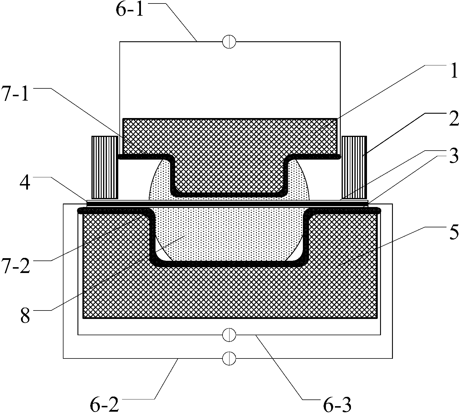
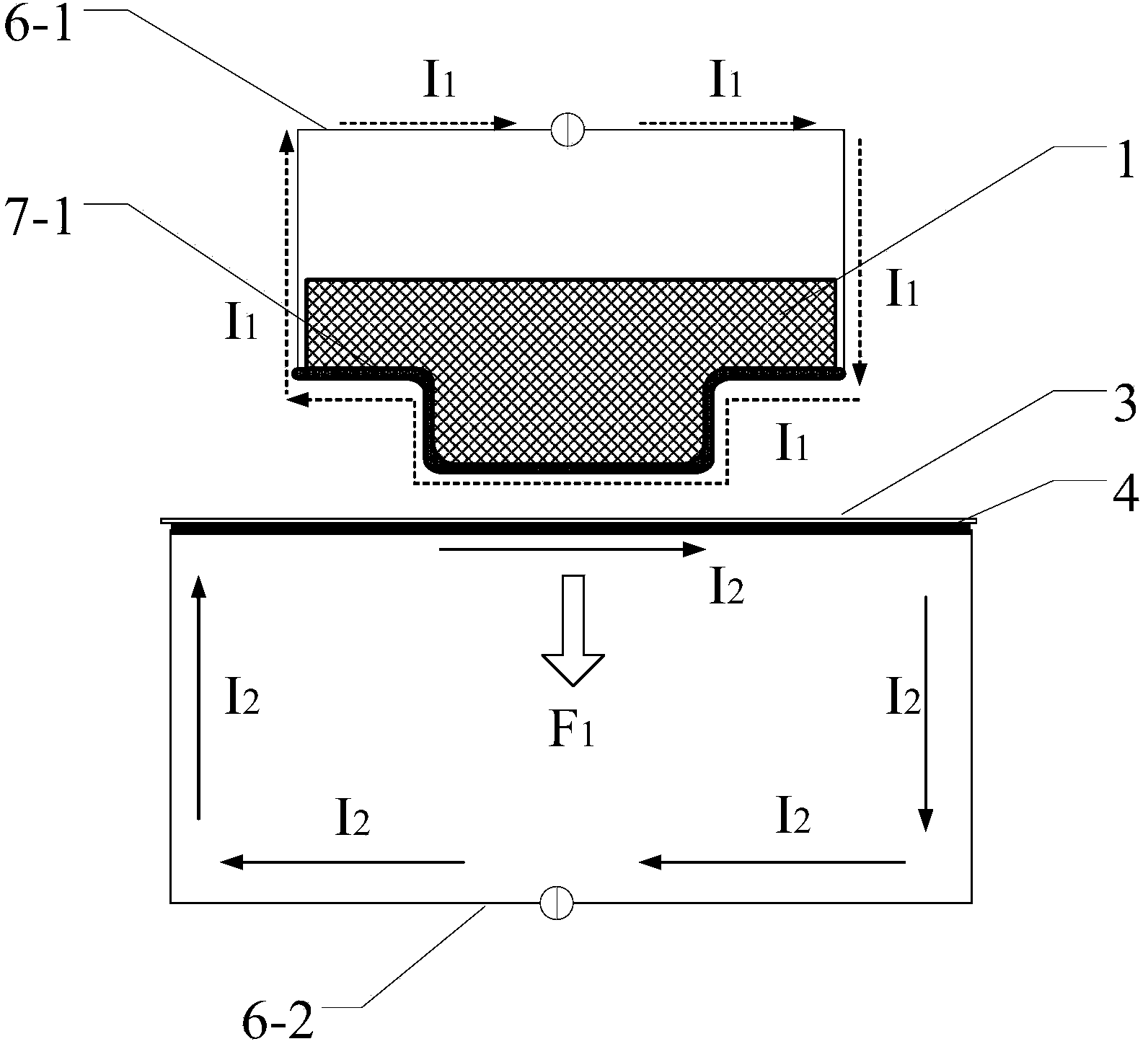
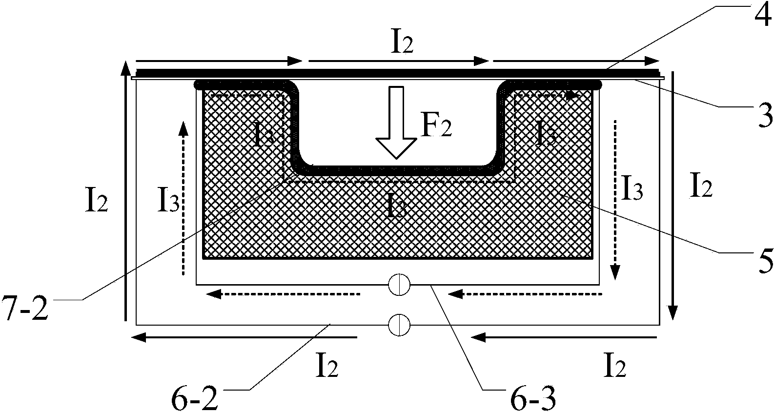
[0027] Specific implementation mode one: as figure 1 As shown, the metal material plastic forming device driven by electromagnetic force includes three high-power power supplies 6-1, 6-2 and 6-3, a blank holder 2, an upper mold 1, a lower mold 5 and a blank holder 2; wherein, The upper mold 1 and the lower mold 5 are respectively placed on the upper and lower sides of the billet 4 to be formed, the lower mold 5 is a concave groove, and the metal blank 4 is placed on the lower mold 5 and pressed with a blank holder 2; The mold 1 is a convex groove matching the lower mold 5, placed on the metal blank 4 and kept at a certain distance therefrom; the convex lower surface of the upper mold 1 is tiled with a layer of brass conductor 7-1 for conduction, and the yellow The copper conductor 7-1 is connected to the high-power power supply 6-1 via a conductive circuit to form a second current path; a layer of brass conductor 7-2 is tiled on the upper surface of the concave groove of the l...

specific Embodiment approach 2

[0030] Embodiment 2: The difference between this embodiment and Embodiment 1 is that the upper mold 1 and the lower mold 5 are made of metal materials, which have good electrical conductivity, so there is no need to tile or wrap the brass conductor 7-1 or 7 -2, directly connected to the high-power power supply 6-1 or 6-3 through the conductive loop to form a current path.

specific Embodiment approach 3

[0031] Specific embodiment three: the difference between this embodiment and specific embodiment one or two is that the high-power power supply 6-1, 6-2, 6-3 is changed to the same set of high-power power supply and draws three branches in parallel through different switches. The current direction and other connection modes are the same as those in the first or second specific embodiment.


PUM


Abstract

The invention discloses a metal material plastic forming method through electromagnetic force driving. The metal material plastic forming method through electromagnetic force driving comprises the following steps that after insulating coatings are sprayed on the upper surface and the lower surface of a metal blank, the metal blank is arranged on a lower mould and is pressed through an edge pressing mould, and a certain interval is kept between an upper mould and the upper surface of the metal blank; current is applied to the metal blank, current opposite to the current of the metal blank in direction is applied to the upper mould, or / and current in the same direction as the current of the metal blank is applied to the lower mould, and downward electromagnetic force generated by mutual action of the current drives the metal blank to deform; the metal blank is attached to the upper surface of a groove of the lower mould after free expansion, mould attaching and other deformation stages under the driving of electromagnetic force, and the metal blank plastically deforms until formation. The invention further discloses a corresponding forming device. By means of the metal material plastic forming method through electromagnetic force driving, stable and continuous electromagnetic force is generated through the current, obviously improves deformation efficiency, increases the plasticity of materials, saves energy, and is suitable for the plastic formation of various metal plates.

Description

technical field [0001] The invention belongs to the field of metal forming processing and manufacturing, and in particular relates to a method and device for plastic forming of metal materials driven by electromagnetic force, which are mainly used for bulging of metal plates, especially superplastic bulging. Background technique [0002] Sheet metal forming of metal materials has a long history, and today it has become a strong technical support for the development of the national economy and an important part of advanced manufacturing technology. The development of sheet metal forming technology is closely related to important industries such as automobiles, aviation, and aerospace. For light alloys such as titanium alloys and aluminum alloys widely used in the aerospace field, due to their poor plasticity and difficulty in forming at room temperature, the method of inflating and thermal expansion is generally used to realize the forming and manufacturing of parts. The gen...

Claims


Application Information

Patent Timeline
IPC IPC(8): B21D26/14B21D37/10
Inventor 李亮熊奇
Owner HUAZHONG UNIV OF SCI & TECH
Why Eureka
Try Eureka