
Method for preparing wave-shaped junction surface metal laminated plate through laser cladding

A technology of laser cladding and joint surface, which is applied in the direction of metal material coating process and coating, and can solve problems such as cracks and differences in physical properties

Inactive Publication Date: 2014-08-06
DALIAN UNIV OF TECH
View PDF1 Cites 8 Cited by
  • Summary
  • Abstract
  • Description
  • Claims
  • Application Information

AI Technical Summary

Problems solved by technology

[0004] In view of the differences in material and physical properties of metal laminates along the plate thickness direction, the cladding and base bonding surfaces of existing rolling metal laminates (substrate thickness 0.8-3.0mm, cladding thickness 0.09-0.25mm) and other preparation methods belong to Planar bonding, usually with defects such as cracks

Method used


Image

  • Method for preparing wave-shaped junction surface metal laminated plate through laser cladding
  • Method for preparing wave-shaped junction surface metal laminated plate through laser cladding
  • Method for preparing wave-shaped junction surface metal laminated plate through laser cladding

Examples


Embodiment

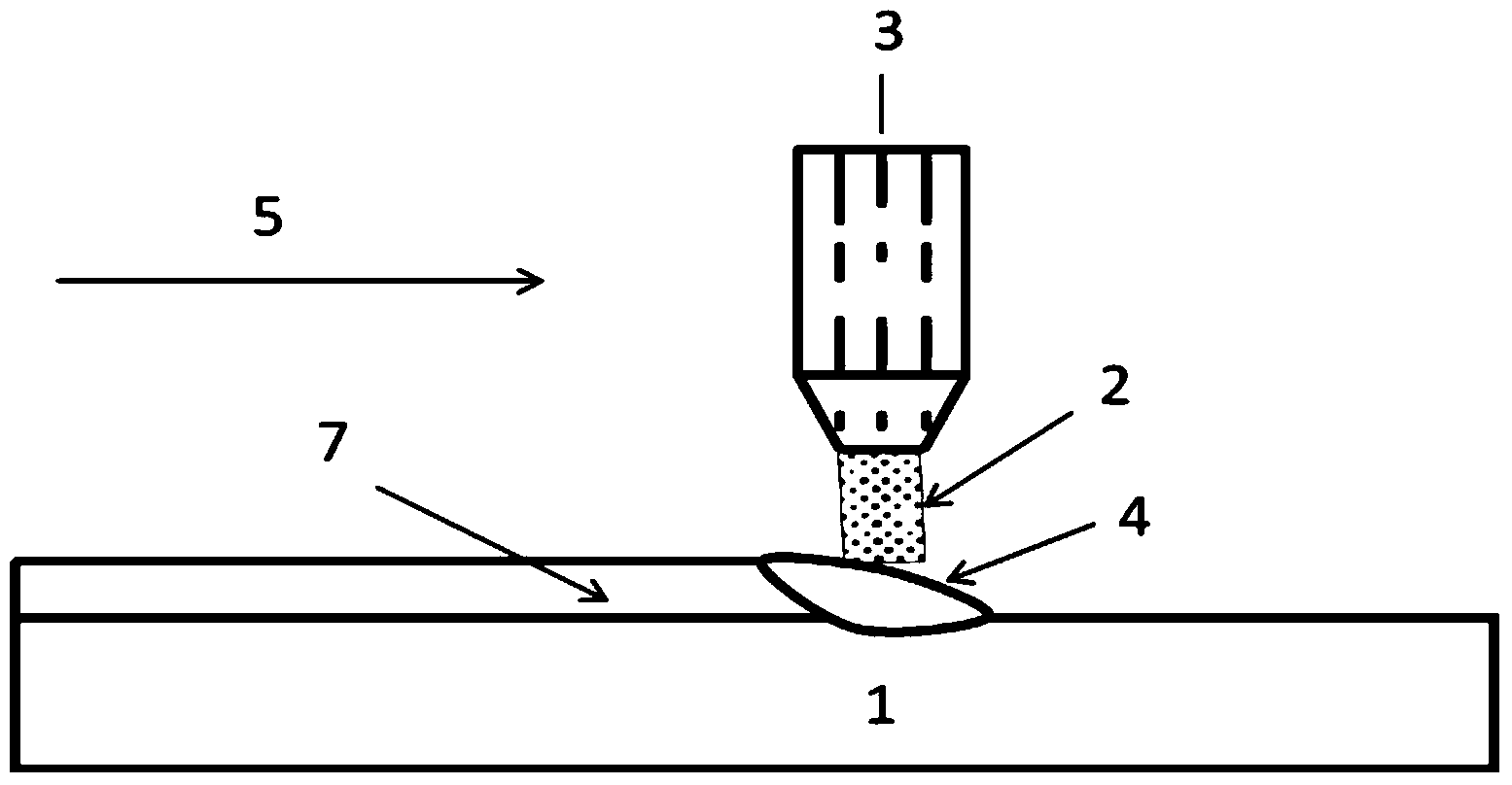
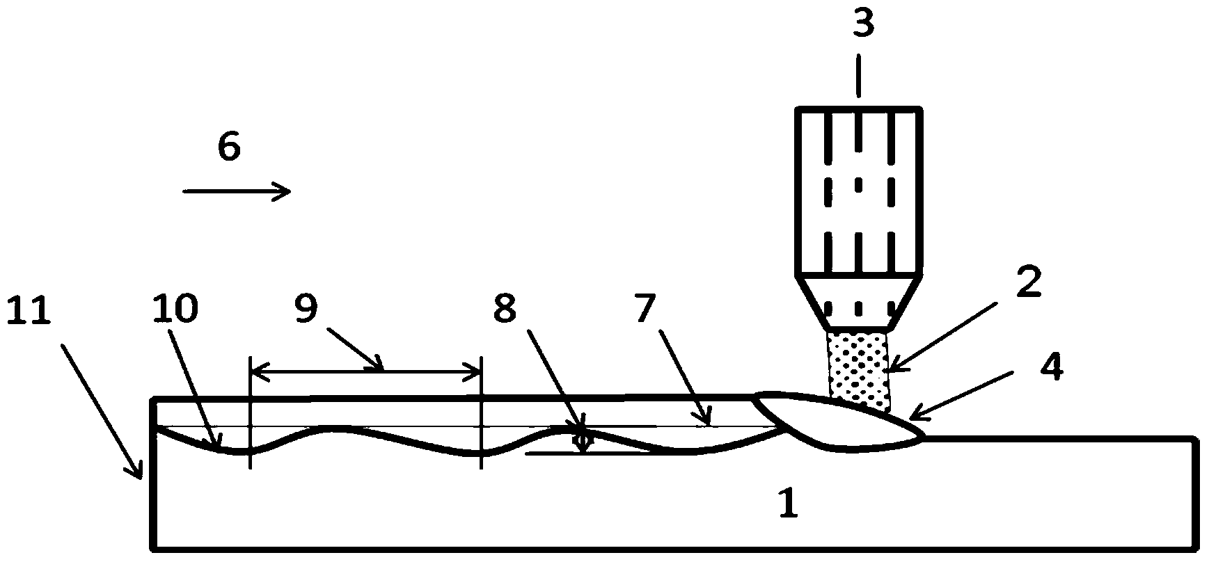
[0015] Before laser cladding, the composite surface of the carbon steel plate is ground to reveal a fresh, flat and clean processed surface, which is beneficial to the mutual diffusion between the two metal atoms during the cladding process and realizes metallurgical bonding. At the same time, the 304 stainless steel powder is dried to improve the fluidity of the powder, and argon is used as the protective gas. A continuous Nd:YAG solid-state laser is used, the power is 550-640W, the scanning speed is 300-500mm / min, the powder feeding amount is 2g / min, the overlap coefficient is 0.3, and the spot diameter is 2mm. Place the carbon steel substrate 1 on the laser processing workbench, turn on the laser beam 3 to irradiate the surface of the plate carbon steel substrate 1, and at the same time convey the coating stainless steel powder 2 coaxially and synchronously, and irradiate and heat the high energy density laser beam 3 to make the coating The surface of the layer powder 2 and...


PUM

PropertyMeasurementUnit
thicknessaaaaaaaaaa
yield strengthaaaaaaaaaa

Abstract

The invention belongs to the technical field of metal laminated plate laser cladding preparation, and relates to a method for preparing a wave-shaped junction surface metal laminated plate through laser cladding. The method comprises the following steps: placing a metallic matrix on a workbench of a laser machine, irradiating the surface of the metallic matrix through laser beams, and irradiating and heating the metallic matrix through laser beams with the laser power of 550-640w and the scanning speed of 300-500 mm / min; conveying cladding powder at the powder feeding speed of 1.5-2.5 g / min coaxially and synchronously under the protection of inert atmosphere to enable partial surfaces of the cladding powder and the metallic matrix to be melted to generate a molten pool, and cladding in the scanning direction through laser beams so as to form a single-track cladding layer; continuously scanning through moving an overlapping distance with the overlapping coefficient of 0.3-0.4 in the overlapping direction perpendicular to the scanning direction so as to form a double-track cladding layer, and repeatedly scanning, so as to form a wave-shaped junction surface metal laminated plate on the surface of the metallic matrix. The yield strength and ductility of the laminated plate provided by the invention reach the standard of a stainless steel laminated plate.

Description

technical field [0001] The invention belongs to the technical field of laser cladding preparation of metal laminates, and relates to a method for preparing metal laminates with corrugated bonding surfaces by laser cladding. Background technique [0002] Metal laminates are prepared by compounding two or more metal materials with different materials. It not only maintains the original performance characteristics of each layer of materials, but also has the characteristics of being superior to a single material in terms of physical, mechanical and mechanical properties. . Due to the development of high-end carrier engineering such as marine and aviation, materials are required to have high strength, corrosion resistance, high temperature resistance and other properties, and higher requirements are put forward for the performance of materials such as corrosion resistance and wear resistance, and even some special materials require increased material strength. Larger, but small...

Claims


Application Information

Patent Timeline
Patent Type & Authority Applications(China)
IPC IPC(8): C23C24/10
Inventor 王续跃高美娜赵志伟徐文骥王连吉
Owner DALIAN UNIV OF TECH
Learn More