Supercharge Your Innovation With Domain-Expert AI Agents!

Optical Position Measuring Device

A measuring device and optical technology, applied in the direction of measuring device, using optical device, using optical device to transmit sensing components, etc., can solve the problems of using reflective integral measuring tools in the indexing period, and achieve the effect of high insensitivity

Active Publication Date: 2018-03-06
DR JOHANNES HEIDENHAIN GMBH
View PDF7 Cites 0 Cited by
  • Summary
  • Abstract
  • Description
  • Claims
  • Application Information

AI Technical Summary

Problems solved by technology

However, the scanning rule used in DE 10 2007 024349 A1 cannot be used at this time in combination with very small graduation intervals on the side of reflective measuring instruments

Method used


Image

  • Optical Position Measuring Device
  • Optical Position Measuring Device
  • Optical Position Measuring Device

Examples


Embodiment Construction

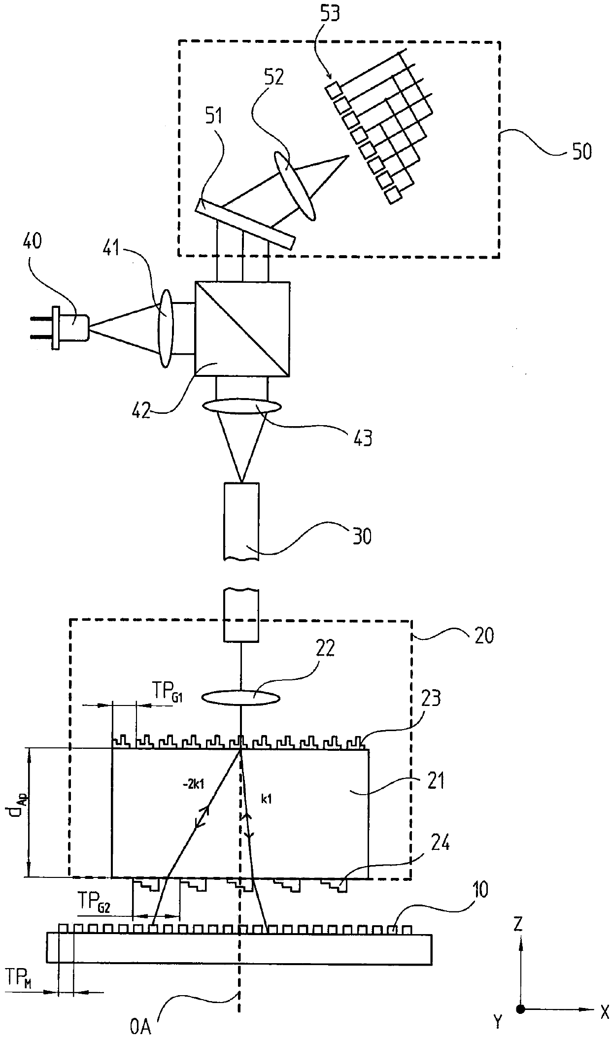
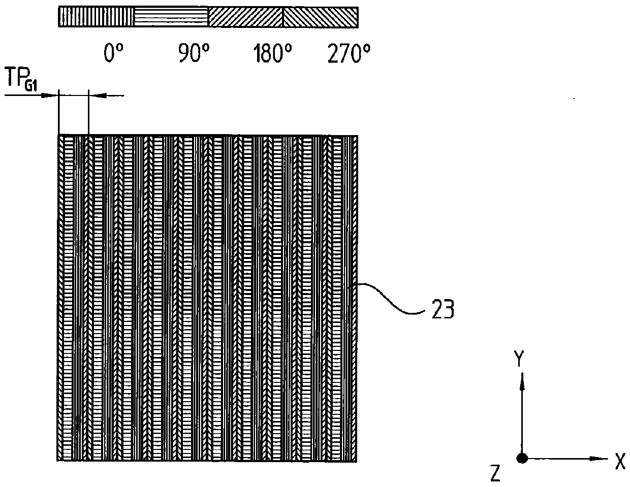
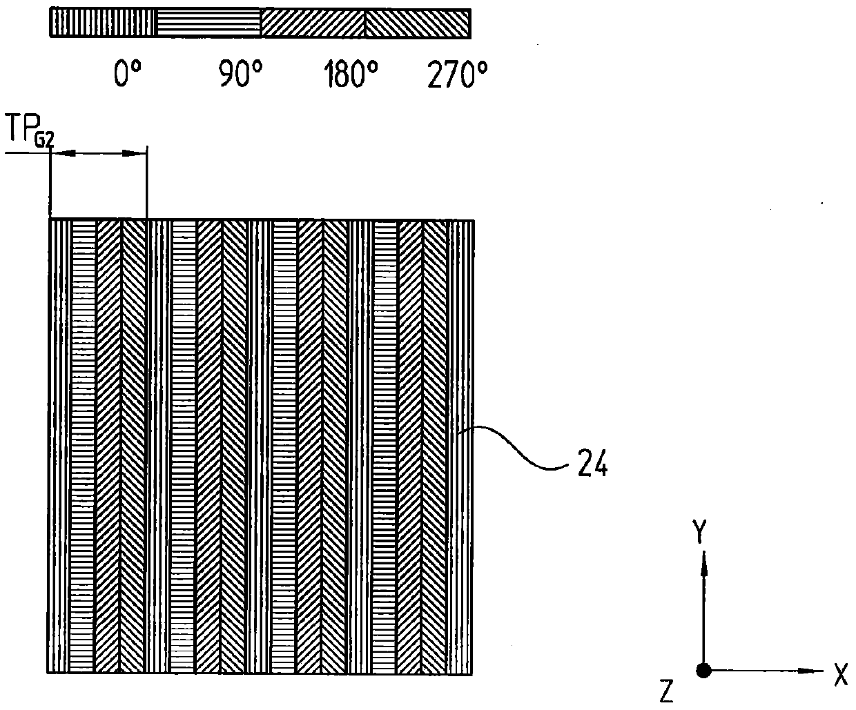
[0045] According to attached figure 1 , 2a and 2b A first embodiment of the position-measuring device according to the invention is explained below.

[0046]The optical position measuring device of the exemplary embodiment shown comprises a linear reflective measuring standard 10 which is arranged displaceably relative to a fiber optic scanning head 20 at least in a given measuring direction x. In this case, the reflective measuring standard 10 can be arranged stationary and the fiber optic scanning head 20 can be arranged movable or the reflective measuring standard 10 can be arranged movable and the fiber optic scanning head 20 can be arranged stationary. Reflective measuring standard 10 and fiber optic scanning head 20 are connected to two—not shown—objects which are movable relative to one another in measuring direction x and whose relative positions can be determined relative to one another. This involves two components of the machine that are movable relative to one ano...


PUM


Abstract

The invention relates to an optical position-measuring device for generating a plurality of phase-shifted scanning signals with respect to the relative position of a fiber optic scanning head and a reflective measuring standard moved for this purpose in at least one measuring direction. In the fiber optic scanning head, the scanning plate is arranged in front of the measuring standard-side end of the optical fiber. This enables a wavelength-dependent encoding of the phase-shifted scanning signal. This is done by splitting the radiation beam impinging on the scanning plate into at least two sub-beams which act on the reflective measuring standard and then interfere with each other recombinedly in order to generate a phase-shifted scanning signal. The sub-beams travel different optical path lengths between separation and recombination.

Description

technical field [0001] The invention relates to an optical position measuring device. Background technique [0002] A known optical position measuring device includes a measuring standard and a scanning unit that moves relative to it. Light sources, photodetector components and other optical components such as lenses, gratings and the like are usually arranged in the scanning unit. For certain applications, all these components may be used, but the scanning unit may be designed to be bulky. Furthermore, in certain applications, undesired influences on active components of such scanning units due to electromagnetic interference fields or increased temperatures are also possible. This can also have a thermal influence on the measurement accuracy due to the electrical power loss of the light source. [0003] Solutions for optical position-measuring devices are therefore known in which only a scanning scale and a relatively movable, passive fiber optic scanning head are arran...

Claims


Application Information

Patent Timeline
Patent Type & Authority Patents(China)
IPC IPC(8): G01D5/26G01D5/38
CPCG01D5/266G01D5/268G01D5/38G01B11/14
Inventor 卡斯滕·萨恩迪格
Owner DR JOHANNES HEIDENHAIN GMBH
Features
  • R&D
  • Intellectual Property
  • Life Sciences
  • Materials
  • Tech Scout
  • Unparalleled Data Quality
  • Higher Quality Content
  • 60% Fewer Hallucinations
Learn More