MIC attenuator applied to DC and ultrahigh frequency

An attenuator and ultra-high frequency technology, applied in the field of microwave component design, can solve the problems affecting the use of high-frequency broadband microwave stand-alone, the inability to realize the microwave bypass function, and the deterioration of the amplitude-frequency characteristics of the attenuator, so as to achieve engineering application High value, realization of ultra-wideband characteristics, and improvement of in-band amplitude-frequency characteristics

Active Publication Date: 2014-08-06
XIAN INSTITUE OF SPACE RADIO TECH
View PDF4 Cites 12 Cited by
  • Summary
  • Abstract
  • Description
  • Claims
  • Application Information

AI Technical Summary

Problems solved by technology

At the same time, the ground resistance of the attenuator is grounded through punching, and the punching needs to meet the design process requirements of the microwave stand-alone MIC chip and cannot be drilled nearby. The frequency characteristics become worse, and the higher the frequency and the greater the attenuation, the worse the large-frequency characteristics will affect the use of high-frequency broadband microwave stand-alone
Unable to realize the microwave bypass function in the debugging stage of the whole machine, and the flexibility is poor

Method used


Image

  • MIC attenuator applied to DC and ultrahigh frequency
  • MIC attenuator applied to DC and ultrahigh frequency
  • MIC attenuator applied to DC and ultrahigh frequency

Examples


Embodiment Construction

[0024] The specific embodiment of the present invention will be further described below in conjunction with the accompanying drawings.

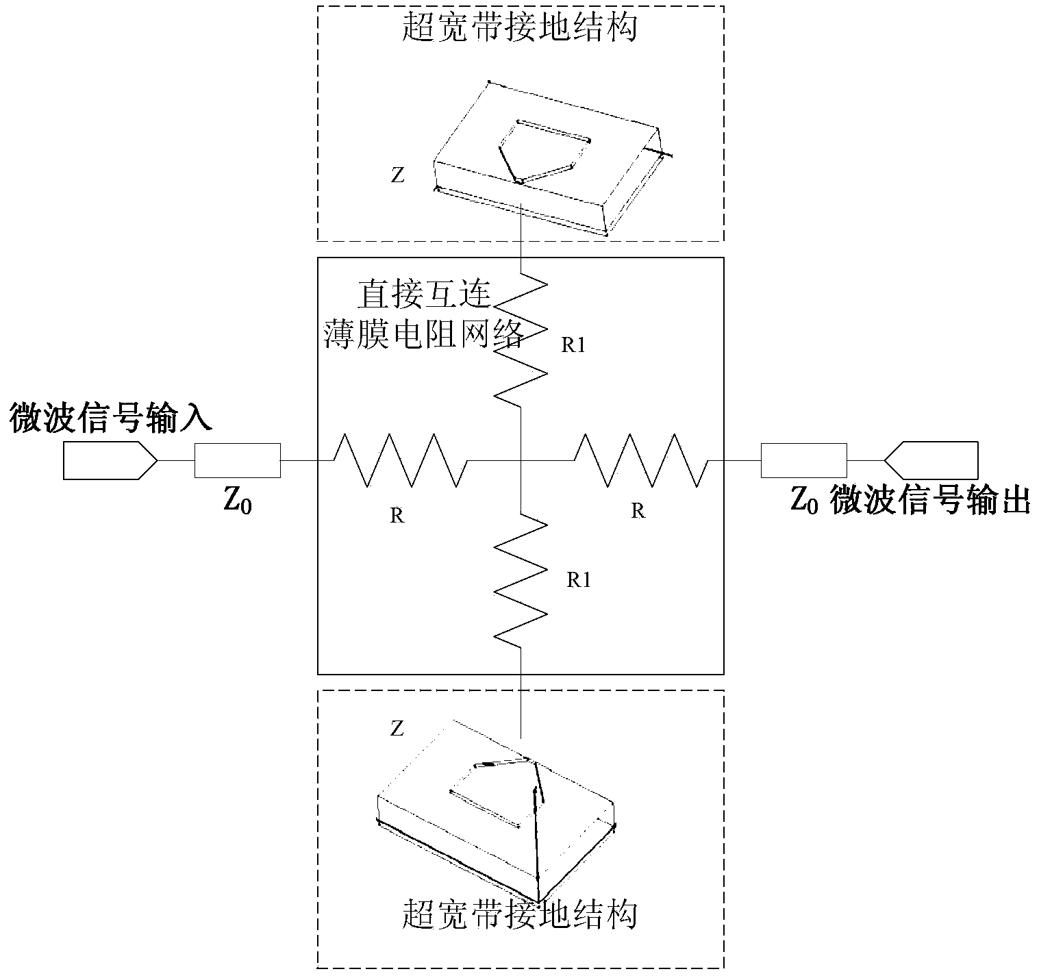
[0025] Such as figure 1 As shown, a MIC attenuator applied to DC to UHF includes: ground structure, thin film resistor network structure, 50 ohm characteristic impedance matching microstrip line Z 0 , where the thin film resistor network structure includes two through resistors R and two ground resistors R1;

[0026] One end of the two through-resistors R and one end of the two ground-to-ground resistors R1 are connected together to form a thin-film resistor network structure with a cross mirror structure, and the other ends of the two through-resistors R are respectively connected to the impedance of the microwave signal input end and the microwave signal output end. The matching microstrip line is connected, and the other ends of the two grounding resistors are respectively connected to the grounding structure.

[0027] The two ground str...


PUM


Abstract

The invention relates to an MIC attenuator applied to DC and ultrahigh frequency. The MIC attenuator applied to DC and ultrahigh frequency is characterized by comprising a grounding structure, a film resistor network structure and characteristic impedance matching microstrip lines, the film resistor network structure comprises two direct-connection resistors R and two resistors R1to ground; the grounding structure is a quarter quasi sector open-circuit microstrip line; one ends of the two direct-connection resistors R are connected with one ends of the resistors R1 to ground to form the film resistor network structure of a criss-cross mirror structure, the other ends of the two direct-connection resistors R are connected with the impedance matching microstrip lines at the microwave signal input end and the microwave signal output end, and the other ends of the two resistors to ground are respectively connected with the grounding structure. According to the MIC attenuator for applying DC to ultrahigh frequency, broadband microwave signal energy can be evenly absorbed, the attenuation values of microwave signals of all frequencies in operation bandwidth are the same, meanwhile, any-frequency reflection signals in the bandwidth can be reduced to an extremely low level, and good matching is achieved.

Description

technical field [0001] The invention relates to a MIC (Microwave Integrated Circiut) attenuator applied to DC (low frequency) to ultra-high frequency, and belongs to the field of microwave component design. Background technique [0002] The MIC attenuator is a very flexible and effective means to adjust the microwave link gain and improve the voltage standing wave ratio of the cascade module, and is widely used in the current microwave machine design. [0003] Traditional MIC attenuators, because there is a microstrip transition line between the direct resistance and the ground resistance of the attenuator, so matching design is required, which restricts the frequency bandwidth and in-band characteristics of the attenuator. Take the 3dB attenuator as an example: Frequency range The narrow absolute bandwidth is 24GHz (4.4 to 28.8GHz), the in-band amplitude flatness is 1.15dB, and the size is 3mm×5.5mm larger. At the same time, the ground resistance of the attenuator is groun...

Claims


Application Information

Patent Timeline
Patent Type & Authority Applications(China)
IPC IPC(8): H01P1/22
Inventor 马美霞张翼张波徐辉王毅袁国靖胡顺平
Owner XIAN INSTITUE OF SPACE RADIO TECH
Why Eureka
Try Eureka