Single-phase power electronic transformer

A technology for power electronics and transformers, which is applied in the power field and can solve the problems that transformers cannot effectively isolate faults, large excitation inrush currents, and cannot be applied to single-phase systems.

Active Publication Date: 2014-08-06
ELECTRIC POWER RES INST OF GUANGXI POWER GRID CO LTD +1
View PDF4 Cites 27 Cited by
  • Summary
  • Abstract
  • Description
  • Claims
  • Application Information

AI Technical Summary

Problems solved by technology

However, the traditional transformer has many disadvantages: (1) It is huge, and with the increase of the voltage level, the volume and weight of the transformer increase sharply; (2) It is sensitive to power quality, and the distortion generated when it is connected to non-linear loads such as uncontrolled rectification The current will enter the power grid through the coupling effect of the transformer, which will pollute the bus grid and cause the quality of power supply to decline; (3) When a grounding short circuit fault occurs on the load side, the traditional transformer cannot effectively isolate the fault, resulting in the expansion of the fault range; (4 ) r

Method used


Image

  • Single-phase power electronic transformer
  • Single-phase power electronic transformer
  • Single-phase power electronic transformer

Examples


Embodiment 1

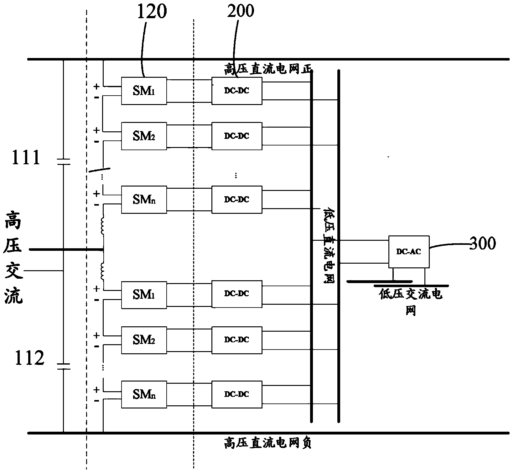
[0027] Embodiment 1 of the present invention provides a single-phase power electronic transformer, such as figure 1 shown, including:

[0028] input stage circuit, intermediate isolation stage and DC-AC inverter 300;

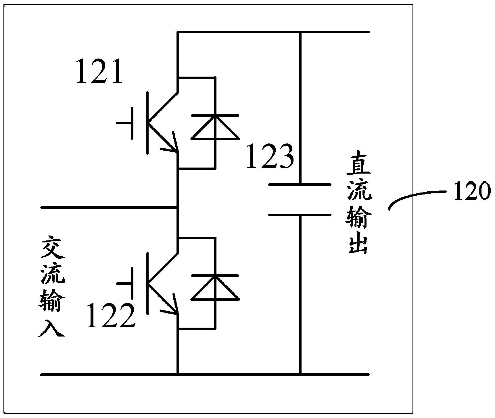
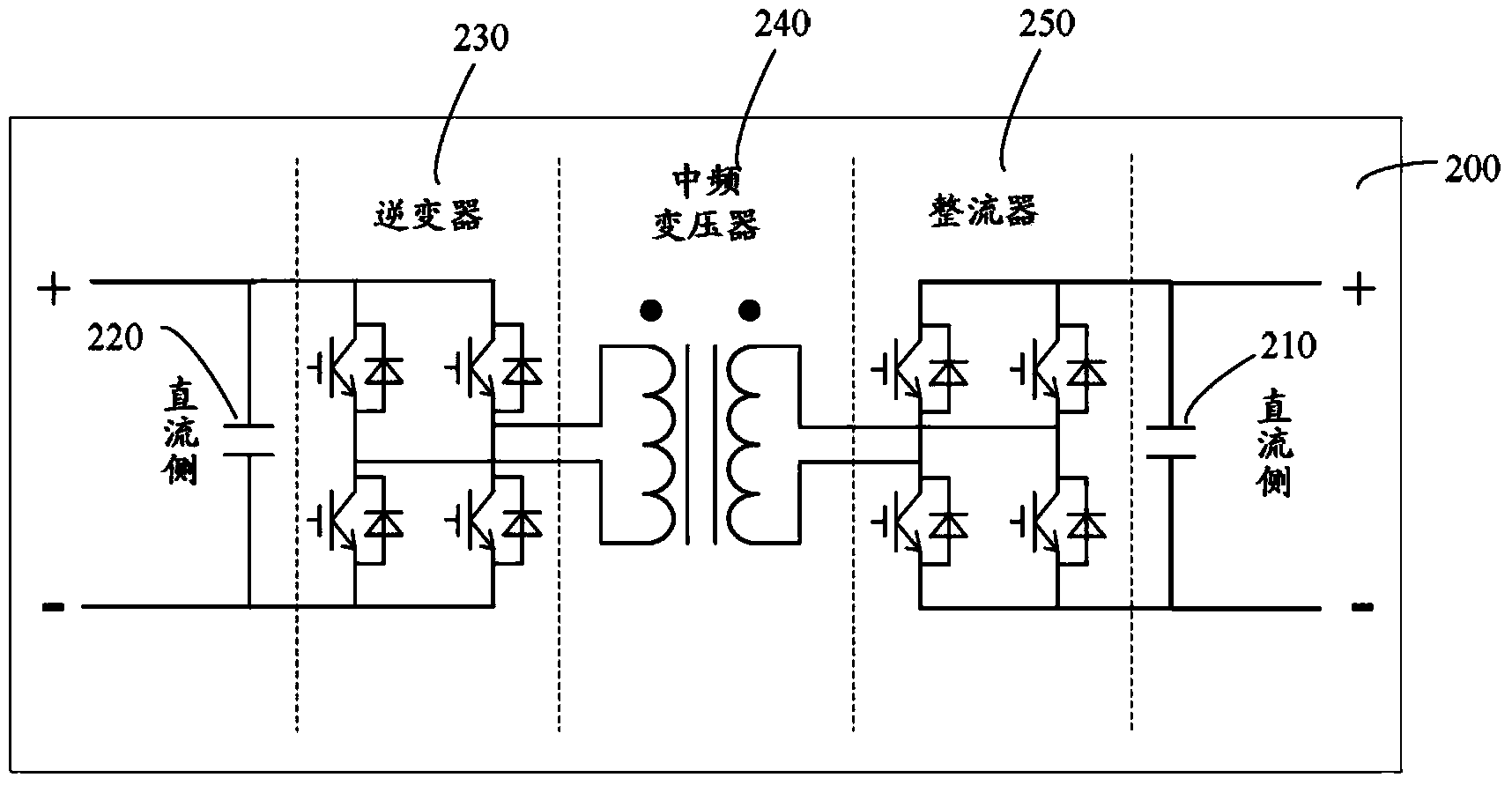
[0029] Wherein, the input stage circuit includes a first bridge arm and a second bridge arm connected in parallel between the positive and negative input terminals of the high-voltage DC bus; the first bridge arm includes two connected capacitors 111 and 112, and the two The connection line between the capacitors is connected to an input end of high-voltage AC; the second bridge arm includes a plurality of modular multilevel SMs (120) connected in series, and the connection line between the upper half bridge arm and the lower half bridge arm is connected to The other input terminal of the high-voltage AC is connected; the intermediate isolation stage includes multiple DC-DC isolators 200, each DC-DC isolator 200 is connected to an SM120, and the output terminal...

Embodiment 2

[0038] The difference between the embodiment of the present invention and the first embodiment lies in that the SM in the input stage shares a capacitor with the inverter connected to it.

Embodiment 3

[0040] The difference between the embodiment of the present invention and the first or second embodiment is that the rectifier of the intermediate isolation stage and the DC-AC inverter share a capacitor.

[0041] Figure 4 The supplied electronic power transformer shows a situation where the SM in the input stage shares a capacitor with the inverter connected to it and the intermediate isolation stage shares a capacitor with the DC-AC inverter.

[0042] The specific implementation process is as follows:

[0043] (1) Input stage

[0044] The structure of the input stage SM control system is as follows Figure 5 As shown, it consists of an inner loop current controller, an outer loop DC voltage regulator, a phase-locked synchronization link and a trigger pulse generation link. The inner loop current controller realizes direct control of the current waveform and phase of the AC side of the inverter to quickly track the reference current. The outer loop DC voltage control rea...


PUM


Abstract

The invention provides a single-phase power electronic transformer. The single-phase power electronic transformer comprises an input-stage circuit, a middle isolating-stage circuit and a DC-AC (direct current-alternating current) inverter, wherein the input-stage circuit comprises a first bridge arm and a second bridge arm; the first bridge arm and the second bridge arm are connected between a positive input end and a negative input end of a high-voltage direct-current bus; the first bridge arm comprises two capacitors which are connected with each other; a connecting line between the two capacitors is connected with an input end of a high-voltage alternating-current bus; an upper half bridge arm and a lower half bridge arm of the second bridge arm comprise a plurality of modular multi-level SM (signal modules); and a connecting line between the upper half bridge arm and the lower half bridge arm is connected with another input end of the high-voltage alternating-current bus. A single-phase half-bridge rectifying circuit is formed by the whole input-stage circuit. The single-phase power electronic transformer is suitable for a high-voltage single-phase rectifier system. Moreover, the power electronic transformer is provided with an alternating-current and direct-current mixed input interface, not only is suitable for an independent alternating-current or direct-current power distribution system, but also is suitable for an alternating-current and direct-current mixed power distribution system. Functions of transformation isolation and power transmission between power grids with different types and voltage classes can be fulfilled.

Description

technical field [0001] The invention relates to the field of electric power technology, in particular to a single-phase power electronic transformer. Background technique [0002] Since the transformer was invented in the 19th century, it has become one of the most basic and important components of the power system. It is widely used in power distribution systems to achieve voltage level conversion and isolation. However, the traditional transformer has many disadvantages: (1) It is huge, and with the increase of the voltage level, the volume and weight of the transformer increase sharply; (2) It is sensitive to power quality, and the distortion generated when it is connected to non-linear loads such as uncontrolled rectification The current will enter the power grid through the coupling effect of the transformer, which will pollute the bus grid and cause the quality of power supply to decline; (3) When a grounding short circuit fault occurs on the load side, the traditional...

Claims


Application Information

Patent Timeline
IPC IPC(8): H02M3/335
Inventor 周柯陈立高立克徐波涂春鸣兰征刘鹏祝文姬吴丽芳欧世锋金庆忍
Owner ELECTRIC POWER RES INST OF GUANGXI POWER GRID CO LTD
Why Eureka
Try Eureka