Rotation piezoelectric energy collecting device

A technology for collecting device and electrical energy, applied in piezoelectric effect/electrostrictive or magnetostrictive motors, electrical components, generators/motors, etc. and other problems, to achieve the effects of reducing vibration and noise, improving power-to-weight ratio, suppressing residual pulsating torque and unbalanced magnetic pull

Inactive Publication Date: 2014-08-06
TIANJIN UNIV
View PDF9 Cites 14 Cited by
  • Summary
  • Abstract
  • Description
  • Claims
  • Application Information

AI Technical Summary

Problems solved by technology

[0005] The invention provides a rotating piezoelectric energy harvesting device. The invention provides the mapping relationship between the number of magnetic steels and the spatial topology and the vibration and voltage output characteristics, and invents the electromechanical perfor...

Method used


Image

  • Rotation piezoelectric energy collecting device
  • Rotation piezoelectric energy collecting device
  • Rotation piezoelectric energy collecting device

Examples


Embodiment 1

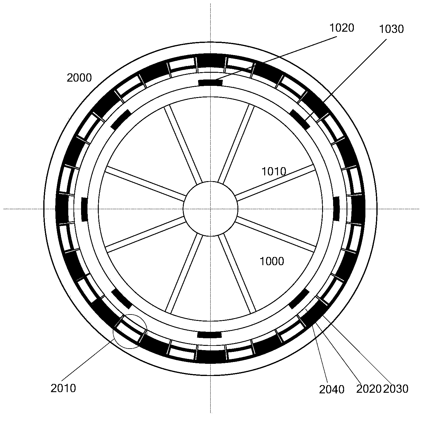
[0129] This embodiment provides a rotating piezoelectric generator with an eight-pole rotor, such as figure 1 shown. The stator and rotor bodies of the device are all made of silicon steel with good magnetic permeability. The magnetic steel is evenly distributed along the circumference of the stator and rotor, and radial magnetization is used to improve power generation efficiency, or tangential magnetization is used to reduce torque ripple. The number of stator magnets can be odd or even, and the number of magnets on the rotor side can be the same or different. The power generation components are connected in series to increase the voltage amplitude, or connected in parallel to reduce the output voltage, which is convenient for the processing of external circuits. In addition, the rotating speed can be adjusted according to the needs to obtain the output voltage of the required frequency. According to the present invention, the rigid-flexible vibration and voltage output c...

Embodiment 2

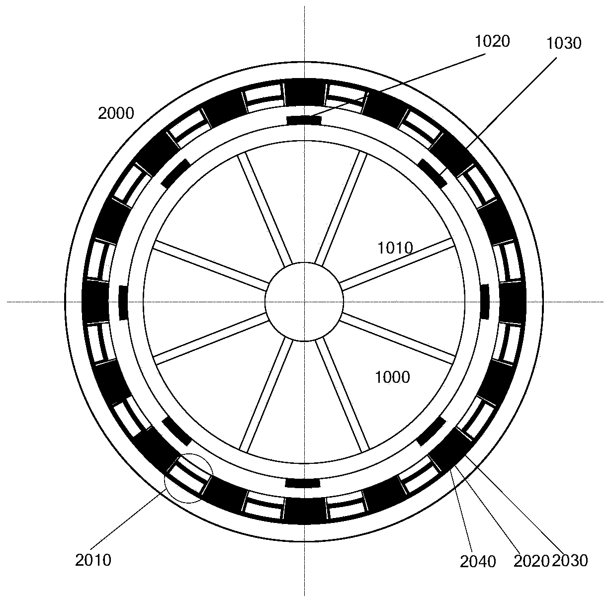
[0133] image 3 As another topological configuration of the present invention, the motor is similar to Embodiment 1, except that the stator and rotor magnets are arranged in opposite polarity. Therefore, the number of magnetic poles of the stator and rotor is an even number, so the magnetic pulling force of the stator magnet steel and the voltage pulsation frequency of the corresponding power generation components are related to the number of pole pairs of the rotor. According to the theoretical analysis of the present invention, the law of rigid-flexible vibration and voltage output described in Table 2 can be obtained. Apparently, the parity of the excitation force harmonics and the number of magnetic poles jointly determine the vibration and voltage output laws of this embodiment.

[0134] Table 2 The vibration and voltage output characteristics of the eight-pole rotor rotating piezoelectric generator (the polarity of the magnetic steel adjacent to the rotor is opposite) ...

Embodiment 3

[0138] In order to increase the output power of the motor and at the same time improve the stress state of the piezoelectric components, Figure 4 Taking the 8-pole stator as an example, a cross-section of the two-stage dislocation axis is given. The misalignment angle of the two stators in the figure is π / 8. The rotor magnets can be arranged with the same polarity or adjacent opposite polarities (not shown). In this embodiment, the vibration characteristics and voltage quality can be optimized by adjusting the number of segments and the misalignment angle. It should be pointed out that although the dislocation method is adopted, the excitation frequency and waveform acting on the piezoelectric component have not changed. In fact, only the excitation force and voltage phase of the two stators have been changed, and the wave response has also been changed. amplitude. It should also be pointed out that if only the force and vibration state in the shaft section are considered,...


PUM


Abstract

The invention discloses a rotation piezoelectric energy collecting device which comprises stators and a rotor. A plurality of piezoelectric assemblies are installed on the inner sides of the stators, and each piezoelectric assembly is composed of stator magnetic steel, a piezoelectric sheet and an insulation sheet; a plurality of pieces of rotor magnetic steel are installed on the outer side of the rotor. The rotation piezoelectric energy collecting device solves the technical problems that the vibration noise is high, the electro-mechanical conversion efficiency is low, and output voltage ripples are large are solved. The stator magnetic steel and the rotor magnetic steel are matched in three modes, the polarities of the stator magnetic steel are the same, and the polarities of the adjacent rotor magnetic steel are opposite; or the polarities of the adjacent stator magnetic steel are opposite, and the polarities of the rotor magnetic steel are the same; or the polarities of the stator magnetic steel and the polarities of the adjacent rotor magnetic steel are both opposite. The stators can be in a discrete piezoelectric stack mode and can be distributed in the circumferential direction of the rotor in an even or grouping symmetry mode. Springs and mass blocks can be further installed in the piezoelectric stacks to sufficiently absorb low-frequency energy. The rotation piezoelectric energy collecting device has the remarkable advantages of being high in electro-mechanical conversion efficiency, high in power-to-weight ratio, small in torque ripple, low in vibration noise, wide in output voltage frequency and the like.

Description

technical field [0001] The invention relates to the technical field of piezoelectric power generation, in particular to a rotating piezoelectric energy collection device. Background technique [0002] Energy shortage is a worldwide problem, and countries have invested a lot of manpower and material resources to find high-quality alternative energy sources. At present, mechanical vibration energy harvesting has attracted extensive attention of engineers and technicians. In the prior art, energy harvesting devices are usually designed in three basic ways: electromagnetic, electrostatic and piezoelectric. Among them, the piezoelectric type has significant advantages such as high energy density, simple structure, and reliable performance, and has become the preferred method. [0003] Piezoelectric energy harvesting utilizes the positive piezoelectric effect to convert mechanical energy into electrical energy. According to the excitation method, the existing technology mainly ...

Claims


Application Information

Patent Timeline
IPC IPC(8): H02N2/18
Inventor 王世宇赵志福谢帮王尧尧张东升
Owner TIANJIN UNIV
Why Eureka
Try Eureka