
Wind power tower

A technology for wind power towers and cylinders, which is applied in wind power generation, wind turbine components, wind engines, etc., can solve problems such as single function, influence on wind energy utilization, and loosening of joints to ensure normal operation, The effect of prolonging the service life and not being easily damaged

Inactive Publication Date: 2014-08-13
HUADIAN HEAVY MACHINERY
View PDF1 Cites 5 Cited by
  • Summary
  • Abstract
  • Description
  • Claims
  • Application Information

AI Technical Summary

Problems solved by technology

In the high temperature season, the ambient temperature of the wind farm becomes higher, and the temperature rises when the inverter, reactor and transformer work, and the heat cannot be dissipated in time, which affects the utilization of wind energy; The impact of major earthquakes or earthquakes will cause slight shaking, and the joints will become loose after a long time. When there is a thunderstorm, the wind power tower on the high mountain is most likely to cause lightning strikes. If there is no lightning protection device, the wind power tower will be greatly reduced. service life
Chinese patent 201120337640.3 discloses a heat dissipation device that uses the wind power tower itself to dissipate heat. It includes a tower made of closed steel plates. A fan is installed on the top of the tower. The air supply pipe at the bottom of the tower, the upper opening of the air supply pipe is connected to the outlet of the fan, and the lower opening of the air supply pipe faces the heating element that needs to be dissipated. This device can achieve the effect of heat dissipation, but it can only solve the heat dissipation problem and has a single function , and cannot meet the numerous demands of the market for wind power towers

Method used


Image

  • Wind power tower
  • Wind power tower

Examples


Embodiment Construction

[0010] The present invention will be further described below in conjunction with accompanying drawing:

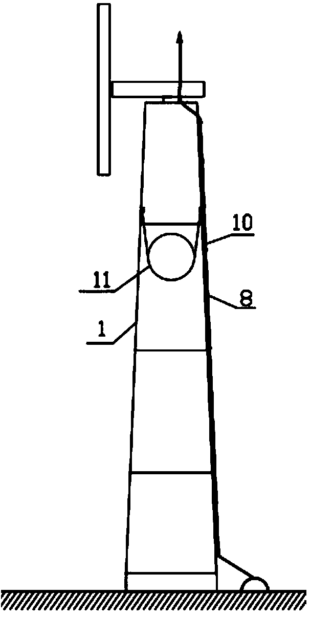
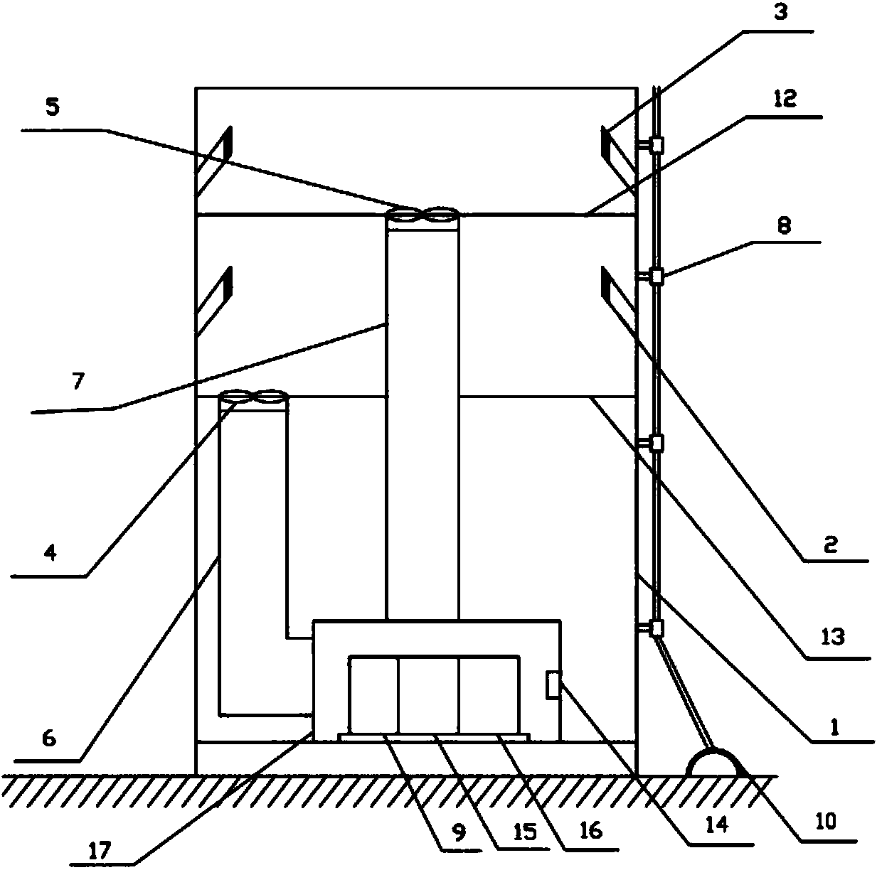
[0011] In the figure, 1. Cylinder body, 2. Ventilation pipe, 3. Filter screen, 4. Fan A, 5. Fan B, 6. Air supply pipe, 7. Air outlet pipe, 8. Insulator, 9. Frequency converter, 10 , lightning protection device, 11, wind damper, 12, upper partition plate, 13, lower partition plate, 14, temperature control device, 15, reactor, 16, transformer, 17, studio.

[0012] Such as figure 1 , figure 2 As shown, the lightning protection device 10 is arranged outside the cylinder body 1, and is fixedly connected with the cylinder body 1 with an insulator 8. The ventilation pipe 2 is fixedly connected on the inner wall of the cylinder body 1. The ventilation pipe 2 is divided into upper and lower layers, and each layer is composed of several Two ventilation pipes 2 form a circle, and the interval between the ventilation pipe 2 and the ventilation pipe 2 is the same. , the lower partit...


PUM


Abstract

The invention relates to a wind power tower which belongs to the field of wind power generation equipment. The wind power tower comprises a tower body, ventilating pipes, an insulator and a wind damper, wherein a lightning arrester is arranged outside the tower body and is fixedly connected with the tower body by the insulator; the ventilating pipes are fixedly connected to the inner wall of the tower body, and a filter screen is arranged on one end of each ventilating pipe; an air supply pipe is connected with a lower flat partition, a fan A is arranged on the top end of the air supply pipe, an air outlet pipe is connected with an upper flat partition, a fan B is arranged on the top end of the air outlet pipe, the lower ends of the air outlet pipe and the air supply pipe are connected with the upper surface and the side surface of an operating room, respectively, and the insulator, a frequency converter, an electric reactor, a transformer and a temperature control device are arranged in the operating room; the wind damper is arranged at the upper part of the wind power tower, and the distance from the wind damper to the bottom of the wind power tower is about three quarters of the length of the wind power tower; lightning stroke can be led into underground by the lightning arrester so as to prevent the tower body and equipment in the tower body from being damaged; the ventilating pipes, the air supply pipe, the air outlet pipe, the fan A and the fan B are matched with one another so as to effectively dissipate heat and cool; the wind damper can be used to relieve earthquake shaking and rocking of the tower body due to strong wind.

Description

[0001] technical field [0002] The invention belongs to the field of wind power generation equipment, in particular to a wind power tower. Background technique [0003] Wind energy is a clean, safe, and renewable green energy. The use of wind energy has no pollution to the environment, no damage to the ecology, good environmental and ecological benefits, and is of great significance to the sustainable development of human society. [0004] At present, the domestic wind power industry technology is gradually mature, and wind power towers are widely used in coastal areas, mountains, plains and other places with sufficient wind energy. It cannot be installed, or the quality cannot be guaranteed after installation, which increases the maintenance cost and causes a waste of wind energy. [0005] The vast majority of wind power towers are connected in sections, and the end of each section has a flange welded with the tower body. The connection between the sections is to lock the...

Claims


Application Information

Patent Timeline
Patent Type & Authority Applications(China)
IPC IPC(8): F03D11/04F03D11/00
CPCY02E10/728
Inventor 侯艳华胡建新
Owner HUADIAN HEAVY MACHINERY
Learn More