
Wind power generation system based on full wave chop-control rectifying circuits

A technology of wind power generation system and rectifier circuit, which is applied in wind power generation, irreversible AC power input conversion into DC power output, single-grid parallel feeding arrangement, etc. The effect of low maintenance cost, simple control and protection, and simple system structure

Inactive Publication Date: 2014-08-13
郭高朋
View PDF0 Cites 5 Cited by
  • Summary
  • Abstract
  • Description
  • Claims
  • Application Information

AI Technical Summary

Problems solved by technology

However, due to the inherent shortcomings of traditional AC-DC converters, the wind power generation system with DC series structure is only in the early research stage, and has no practical value, and its performance does not meet the requirements of wind power generation systems: AC side current distortion is small , the DC side output voltage can be adjusted arbitrarily from 0 to the maximum value, the converter technology is mature, the cost is low, the loss is small, the control is simple, and the reliability is high.
The voltage on the DC side of the thyristor-based phase-controlled rectifier can be adjusted arbitrarily, but the current distortion on the AC side is large, which has a significant impact on the performance and life of the wind turbine; the wind power converter (Voltage Source Converter, VSC) based on the voltage source converter ) The distortion rate of the current waveform on the AC side is very small, but the voltage on the DC side cannot be adjusted arbitrarily, so it is not suitable for a wind power system in series with DC; Wind power converters (Current Source Convertor, CSC) based on fully-controlled current source converters The distortion rate of the current waveform on the AC side is small, and the voltage on the DC side can be adjusted arbitrarily, but the technology is immature, the loss is large, the control is difficult, and there are almost no other applications, and the research on CSC is also very limited, just staying in the theoretical research stage

Method used


Image

  • Wind power generation system based on full wave chop-control rectifying circuits
  • Wind power generation system based on full wave chop-control rectifying circuits

Examples


Embodiment Construction

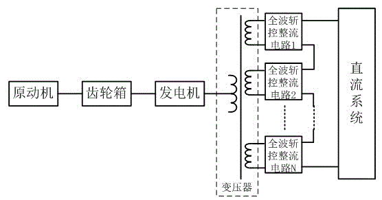
[0049] A wind power generation system based on a full-wave chopper-controlled rectifier circuit is characterized in that it is composed of a prime mover, a gear box, a generator, a transformer, N full-wave chopper-controlled rectifier circuits and a DC system.

[0050] Among them, the prime mover converts the wind force into the mechanical energy of the wind blade rotation, and after being accelerated by the gearbox, it drives the rotor of the generator to rotate, and the generator converts the mechanical energy into electrical energy.

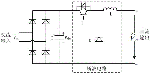
[0051] The output of the generator is connected to the primary winding of the transformer, and the secondary winding of the transformer has N mutually isolated coils, and each coil is connected to the AC input of the full-wave chopper-controlled rectifier circuit.

[0052] The DC outputs of the N full-wave chopper-controlled rectifier circuits are connected in series, and then connected to the DC system.

[0053] The DC system is used for the co...


PUM


Abstract

The invention provides a wind power generation system based on full wave chop-control rectifying circuits. Based on the system, a wind power generation, binding and grid-connected system based on direct current side series connection can be formed. The wind power generation system is composed of a prime motor, a gearbox, an engine, a transformer, the N full wave chop-control rectifying circuits and a direct current system. Alternating current side currents of the full wave chop-control rectifying circuits are sine waves, and direct voltages capable of being adjusted from 0 to the maximum value are output from the direct current sides. The wind power generation system is simple in control, good in performance, easy to obtain, and good in expansibility.

Description

technical field [0001] The invention relates to a power conversion method for a wind power generation system, and more specifically, relates to a wind power generation system based on a full-wave chopper-controlled rectifier circuit. Background technique [0002] With global warming, continuous increase in carbon dioxide emissions and the gradual depletion of traditional fossil energy, people are paying more and more attention to renewable energy, while the development technology of onshore solar and wind energy has been relatively mature and has been developed on a large scale. development, and offshore wind power is very difficult to construct and maintain because it is far from the shore. For wind farms far from the shore, DC transmission has become the only alternative power transmission solution. The method of collecting and converting electric energy in the power station is as follows: the wind generator adopts asynchronous double-fed wind generator, and the speed is i...

Claims


Application Information

Patent Timeline
IPC IPC(8): H02M7/12H02J3/38
CPCY02E10/763Y02E10/76
Inventor 郭高朋
Owner 郭高朋
Learn More