Device and method for removing molten steel slag inclusion in continuous casting tundish

A continuous casting tundish and tundish technology, which is applied in the direction of casting molten material containers, casting equipment, manufacturing tools, etc., can solve the problems of small quantity, large pores of air curtain permeable bricks, large diameter of argon bubbles, etc., and achieve low production cost , high bubble density, and the effect of reducing production costs

Active Publication Date: 2014-08-20
LAIWU STEEL YINSHAN SECTION CO LTD
View PDF10 Cites 21 Cited by
  • Summary
  • Abstract
  • Description
  • Claims
  • Application Information

AI Technical Summary

Problems solved by technology

[0005] In the actual production process, after long-term production practice, it has been proved that the existing flow control device and the continuous casting tundish air curtain retaining wall technology have technical defects: (1) the continuous casting machine tundish is set by The combination of turbulence controller, retaining wall and retaining dam can only effectively remove inclusions with equivalent diameter greater than 50 μm, but cannot effectively remove tiny inclusions with equivalent diameter less than 50 μm; in the tundish of continuous casting machine The technical scheme of setting air curtain permeable bricks inside can only effectively remove tiny inclusions with equivalent diameters less than 50 μm, but cannot effectively remove inclusions with equivalent diameters greater than 50 μm; (2) The installation positions of existing air curtain permeable bricks are: Technical defect: The existing air curtain permeable brick replaces the dam or is installed in the pouring area between the dam and the upper nozzle of the tundish, and the actual application effect of effectively removing tiny inclusions with an equivalent diameter of less than 50

Method used


Image

  • Device and method for removing molten steel slag inclusion in continuous casting tundish
  • Device and method for removing molten steel slag inclusion in continuous casting tundish
  • Device and method for removing molten steel slag inclusion in continuous casting tundish

Examples


Embodiment 1

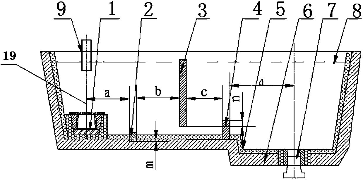
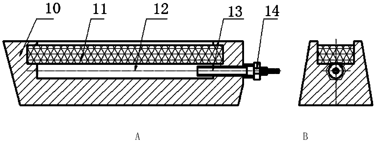
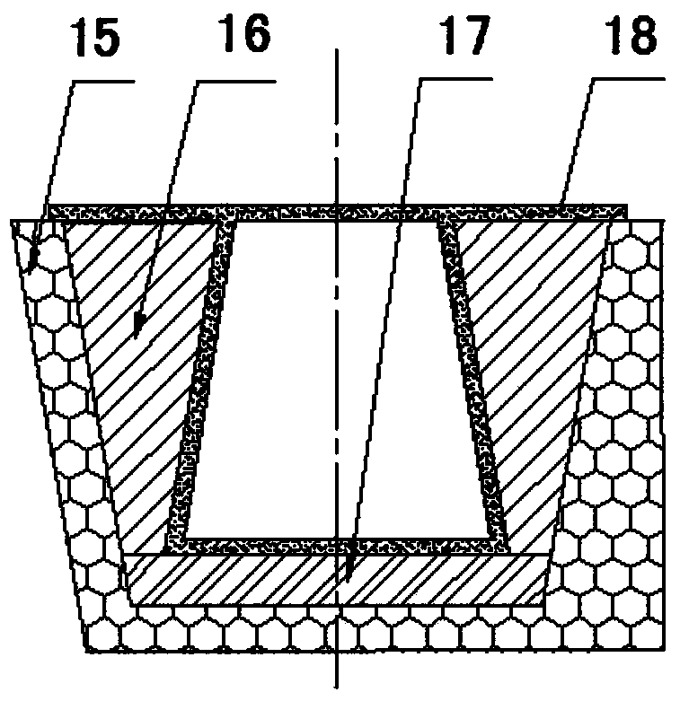
[0038] A device for removing molten steel inclusions in a continuous casting tundish, with a structure such as Figure 1-Figure 5 As shown, it includes turbulence controller 1, air curtain permeable brick 2, retaining wall 3 and retaining dam 4, turbulence controller 1 is installed on the inner side of the working lining of the tundish injection impact zone, and its longitudinal centerline is the same as the length of the tundish. The center line of the nozzle 9 coincides, the two ends of the retaining wall 3 are fixed on the working lining 5 of the tundish wall, the bottom end of the retaining dam is fixed on the working lining 5 at the bottom of the tundish, and the retaining wall 3 is located at the turbulence control Between the device 1 and the dam 4, the air curtain permeable brick 2 is located between the turbulence controller 1 and the retaining wall 3, and the bottom end is fixed on the permanent lining at the bottom of the tundish. The longitudinal centerline of the t...

Embodiment 2

[0044] The device for removing molten steel inclusions in the continuous casting tundish as described in Example 1, the difference is:

[0045] The horizontal distance a between the longitudinal centerline of the turbulence controller 1 and the air curtain permeable brick 2 is 600 mm, the horizontal distance b between the air curtain permeable brick 2 and the retaining wall 3 is 700 mm, and the horizontal distance c between the retaining wall 3 and the retaining dam 4 is 600mm, and the horizontal distance d between the retaining dam and the upper nozzle of the tundish is 1000mm.

[0046] The depth m of the bottom end of the air curtain permeable brick 2 embedded in the permanent lining 6 at the bottom of the tundish is 30mm.

Embodiment 3

[0048] The device for removing molten steel inclusions in the continuous casting tundish as described in Example 1, the difference is:

[0049] The horizontal distance a between the central line of the turbulence controller 1 and the air curtain permeable brick 2 is 400mm, the horizontal distance b between the air curtain permeable brick 2 and the retaining wall 3 is 200mm, and the horizontal distance c between the retaining wall 3 and the retaining dam 4 is 200mm, and the horizontal distance d between the retaining dam and the upper nozzle of the tundish is 1200mm.

[0050] The depth m of the bottom end of the air curtain permeable brick 2 embedded in the permanent lining 6 at the bottom of the tundish is 18mm.


PUM

PropertyMeasurementUnit
Thicknessaaaaaaaaaa
Thicknessaaaaaaaaaa

Abstract

The invention relates to a device and method for removing molten steel slag inclusion in a continuous casting tundish. The device comprises a turbulence controller, air curtain ventilation bricks, parapets and blocking dams, wherein the air curtain ventilation bricks (2) are located between the turbulence controller (1) and the parapet (3) and fixed to a tundish bottom permanent liner, the horizontal distance a between the longitudinal center line of the turbulence controller (1) and the longitudinal center line of the air curtain ventilation bricks (2) ranges from 400 mm to 600 mm, the horizontal distance b between the air curtain ventilation bricks (2) and the parapets (3) ranges from 200 mm to 700 mm, and the horizontal distance c between the parapets (3) and the blocking dams (4) ranges from 200 mm to 700 mm. By means of the method and device, the slag inclusion with the equivalent diameter larger than 50 microns in a continuous casting slab is basically removed, and the amount of micro slag inclusion with the equivalent diameter smaller than 50 microns in the continuous casting slab is reduced by more than 60 percent compared with the amount of the micro slag inclusion removed under the using condition that one tundish is internally provided with the turbulence controller, the parapets and the blocking dams and is reduced by more than 30 percent compared with the amount of the micro slag inclusion removed under the using condition that one tundish is internally provided with the turbulence controller and the air curtain ventilation bricks.

Description

technical field [0001] The invention relates to a device and method for removing liquid steel inclusions in a continuous casting tundish, belonging to the technical field of iron and steel metallurgy continuous casting tundish technology. Background technique [0002] In the tundish of the continuous casting machine, a flow control device composed of a turbulent flow controller, a retaining wall and a dam is installed, which can change the running route of the molten steel in the tundish, prolong the residence time of the molten steel in the tundish, and promote the floating and melting of inclusions. The metallurgical function of removing and reducing the inclusions inside the slab and changing the shape of the inclusions. In recent years, in order to meet the requirements for the control of inclusions in the development and production of high-purity clean steel, the technology of continuous casting tundish air curtain retaining wall has been studied and applied, that is, t...

Claims


Application Information

Patent Timeline
IPC IPC(8): B22D41/00B22D11/117
Inventor 武光君席超
Owner LAIWU STEEL YINSHAN SECTION CO LTD
Why Eureka
Try Eureka