

Electrode structure, electrode, power device and method for manufacturing the same
An electrode structure and power device technology, applied in electrode manufacturing, hybrid/electric double-layer capacitor manufacturing, electrode carrier/current collector, etc. Effect
- Summary
- Abstract
- Description
- Claims
- Application Information
AI Technical Summary
Problems solved by technology
Method used
Image

Examples
example 1
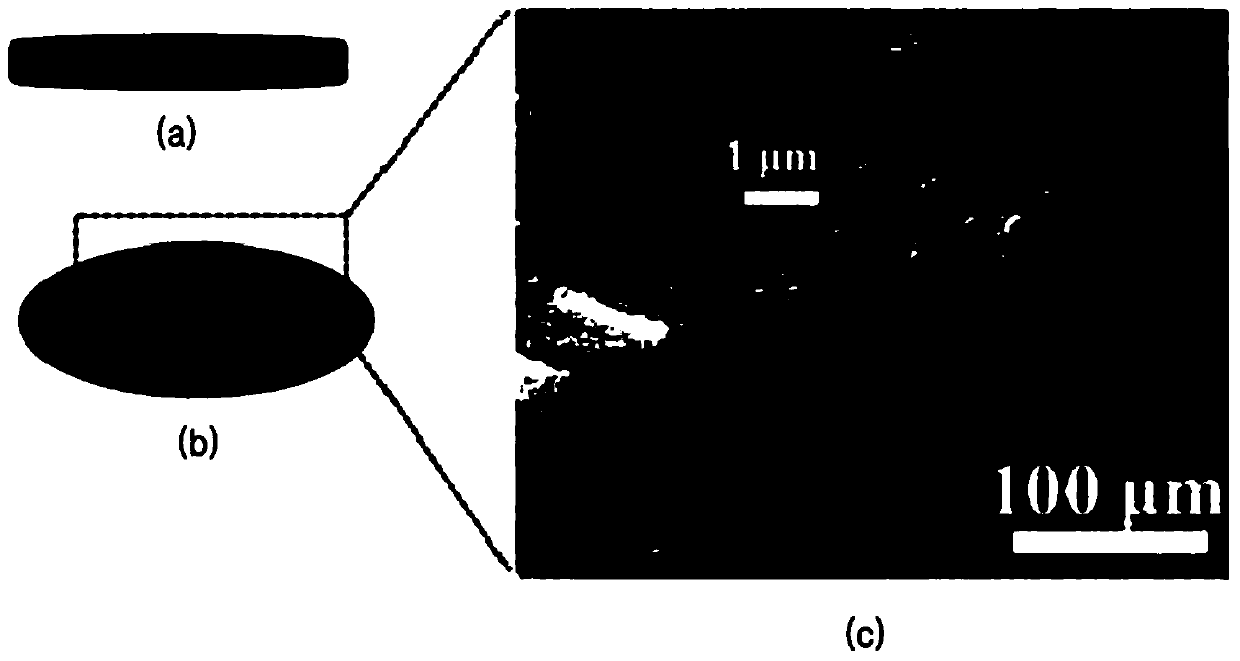
[0108] Graphene oxide was added to deionized water to obtain a solution with a graphene oxide concentration of approximately 1 mg / mL. SWCNT (Hanwha Chemical Co., Ltd., Korea) was added to the solution at about 5 wt% based on the weight of graphene oxide to prepare a mixed solution. The mixed solution was ultrasonicated for about 3 hours by using an ultrasonic cleaner (Power Sonic 470) and dispersed at 6,500 rpm for about 1 hour by using a high-speed mixer (Wise Tis). The concentration of the graphene oxide solution was increased to a range of about 5 mg / mL to about 10 mg / mL by venting through a solvent evaporation tower (BUCHI Corporation, USA). After degassing, about 300 mL to about 500 mL of the graphene oxide solution was injected into a drying rack (30 cm×30 cm). The drying rack containing the graphene oxide solution was placed in the wash station and dried for approximately 24 hours.
[0109] After finishing drying, the graphene oxide film was cut into a size of about 2...
example 2
[0114] Example 2: Sample battery manufacturing
[0115] Fabrication of sample cells was performed for water-based experiments. Prepare two antistatic slides, current collectors (about 1M H 2 SO 4 Ti foil (120 μm, 1 cm × 4 cm) for aqueous solution, and Ni foil (120 μm, 1 cm × 4 cm, Sigma-Aldrich) for 6M KOH aqueous solution), separator (Whatman filter paper), electrolyte (1M H 2 SO 4 aqueous solution, 6M KOH aqueous solution) and polyimide tape.
[0116] First, each current collector was positioned at the center of the slide and the graphene electrode structure was positioned within a range of about 1 cm to about 1.5 cm from the edge of the current collector having dimensions of about 1 cm x 4 cm. Then, the current collector excluding the graphene electrode structure and the support sheet was fixed with polyimide tape. A separator was placed between two electrodes and the two electrodes were fixed with a Teflon tape to prepare each assembled battery. Each assembled batter...
example 3
[0117] Example 3: Coin Cell Manufacturing
[0118] Separators (Celgard, LLC., 3501) and 1M 1-butyl-3-methylimidazolium tetrafluoroborate (BMIM-BF4, Sigma-Aldrich) dissolved in acrylonitrile as electrolyte were used for coin cell fabrication . Regarding the coin cell, since the graphene structure forms a rolled film after being cut open, separate use of the current collector is not required.
[0119] First, the graphene structure obtained in Example 1 was placed at the center of the aluminum bottom case and about 200 μL of electrolyte was dropped on the graphene electrode structure. Thereafter, a separator was placed thereon and about 200 μL of electrolyte was dropped on the separator. The graphene structure obtained in Example 1 was provided as a counter electrode at the center of the case, and the case was sealed to complete the fabrication of the coin cell.
PUM
| Property | Measurement | Unit |
|---|---|---|
| thickness | aaaaa | aaaaa |
| diameter | aaaaa | aaaaa |
| thickness | aaaaa | aaaaa |
Abstract
Description
Claims
Application Information