

Solar photovoltaic charge control device
A solar photovoltaic and charging control technology, applied in photovoltaic power generation, circuit devices, battery circuit devices, etc., can solve problems such as large inrush current, low power loss system efficiency, damage, etc., to eliminate inrush current, reduce switch loss, The effect of improving the performance against electromagnetic interference
- Summary
- Abstract
- Description
- Claims
- Application Information
AI Technical Summary
Problems solved by technology
Method used
Image

Examples
Embodiment Construction
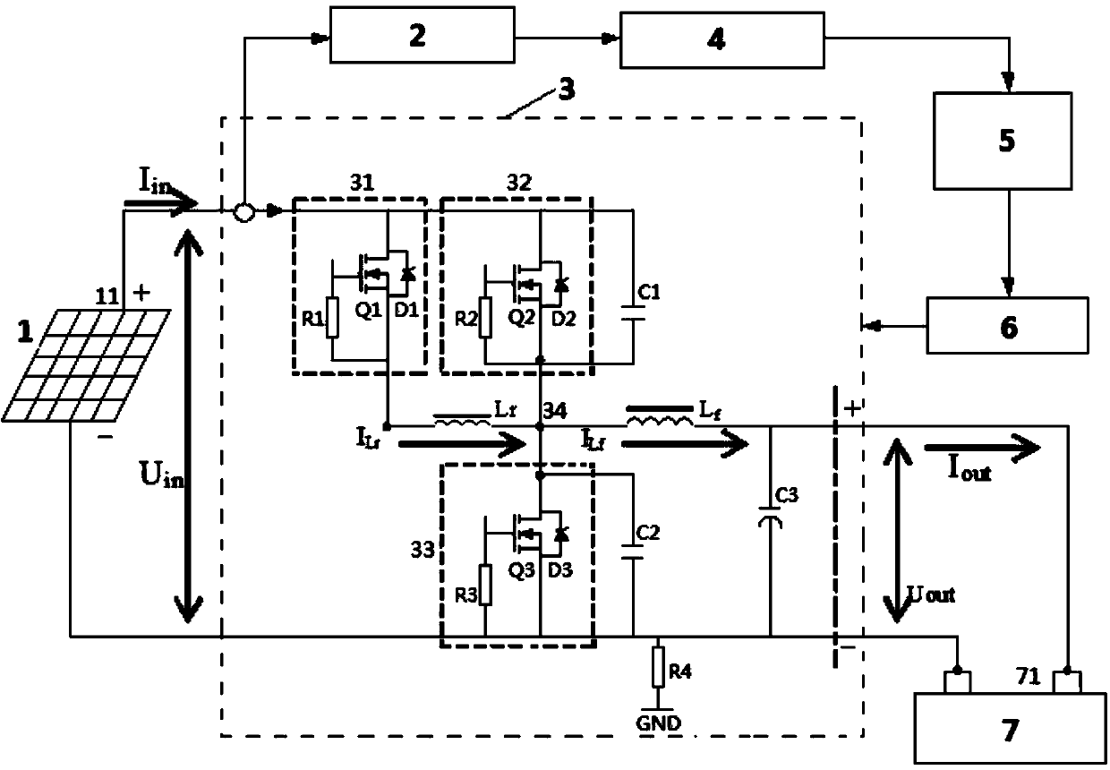
[0032] In order to make the purpose, technical solution and advantages of the present invention clearer, the present invention will be further described in detail below in conjunction with the accompanying drawings and embodiments. It should be understood that the specific embodiment described here is the solar photovoltaic charging control device of the present invention with a single power of 500W, which is only used to explain the present invention, not to limit the present invention. Among them, the charging voltage of the storage battery 7 is 12V, the maximum output voltage of the DC-DC conversion part 3 is 14.8V, and the maximum output current is 40A.
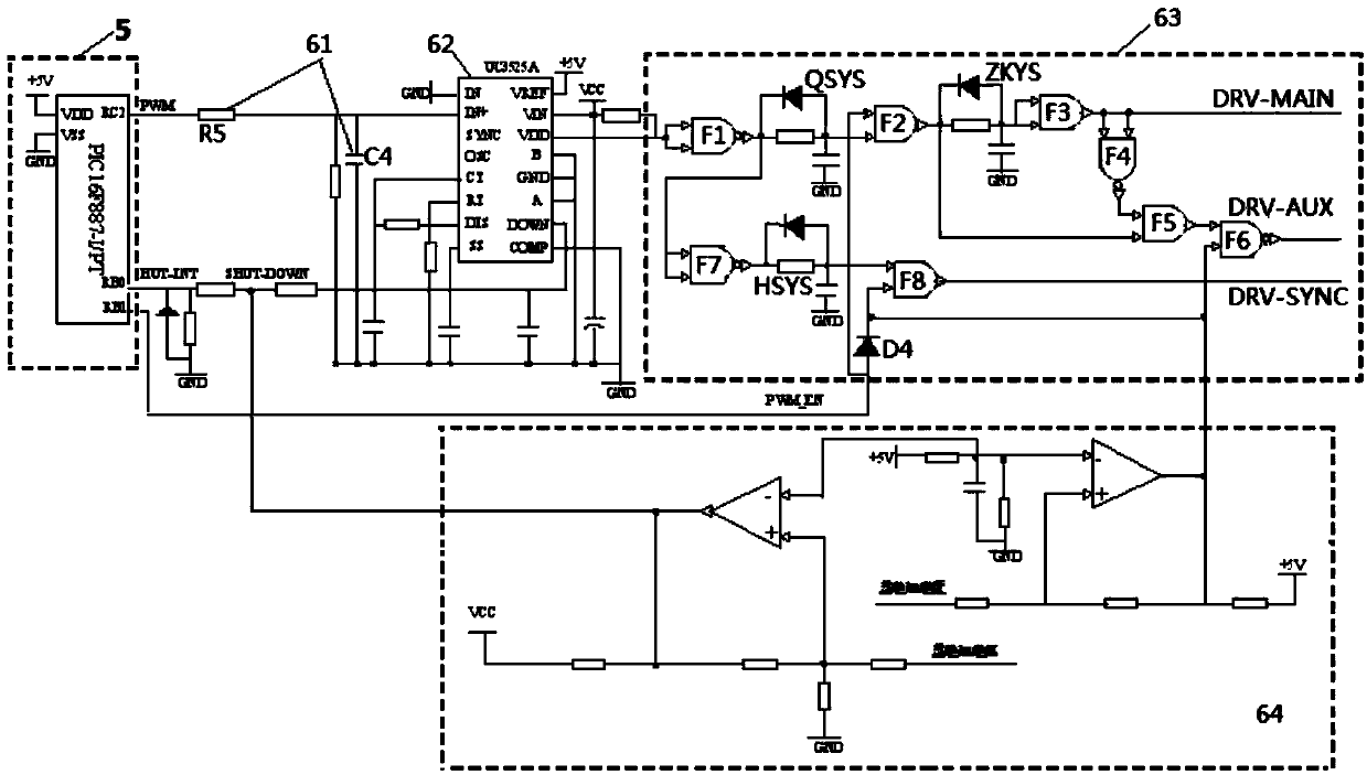
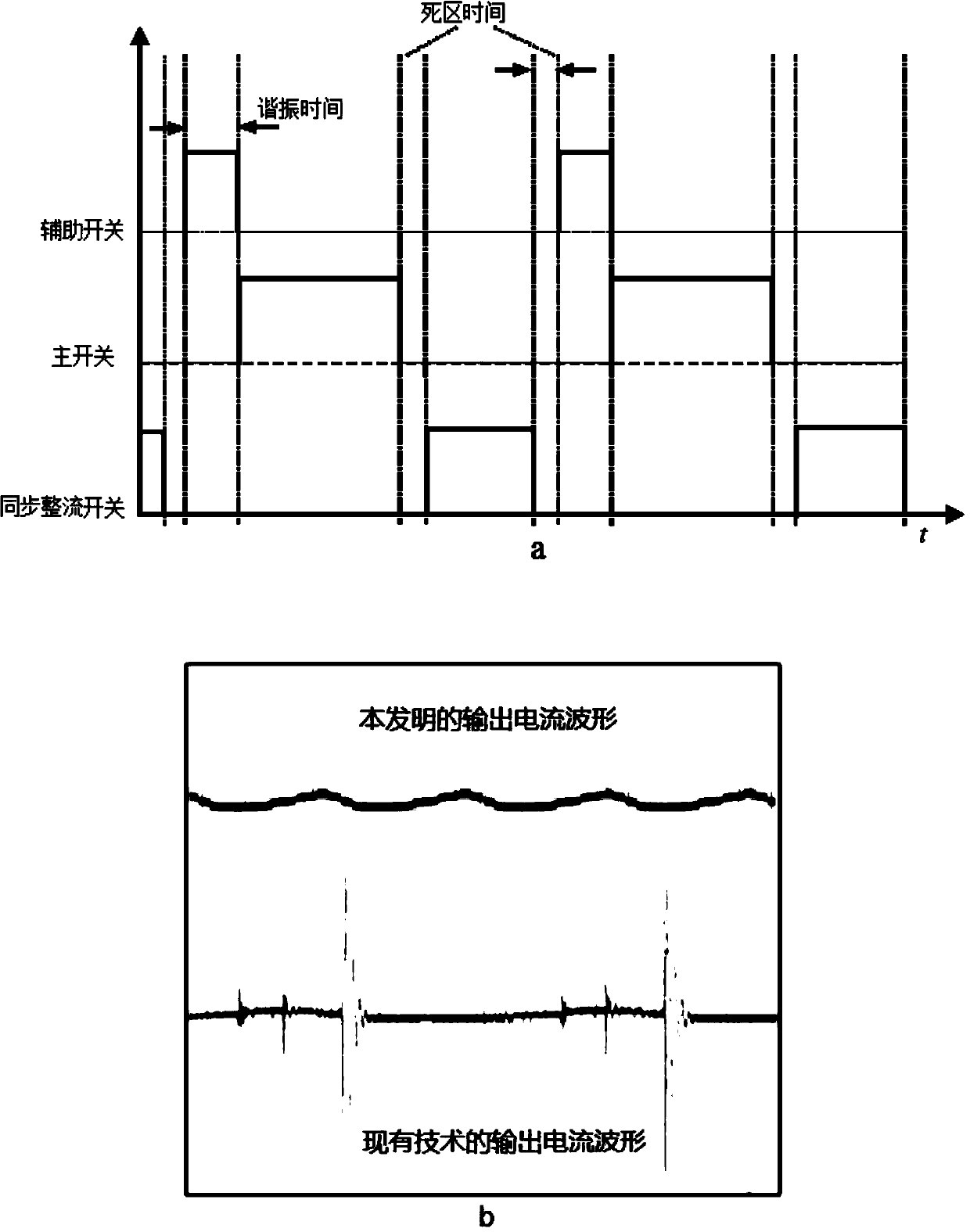
[0033] see figure 1 , figure 2 and image 3a, The basic composition of the solar photovoltaic charging control device is composed of a microprocessor 5, a voltage and current detection part 2, a sampling data conversion part 4, a PWM signal driving part 6 and a DC-DC conversion part 3. The input end of the microproces...
PUM
| Property | Measurement | Unit |
|---|---|---|
| Capacitance | aaaaa | aaaaa |
| Inductance | aaaaa | aaaaa |
Abstract
Description
Claims
Application Information