Equipment for manufacturing large-size metal part in high energy beam additive manufacturing mode and control method of equipment

An additive manufacturing, high-energy beam technology, applied in the field of additive manufacturing, high-efficiency forming, high-energy beam additive manufacturing equipment and control fields for large-sized metal parts, to improve forming efficiency and processing quality, improve forming efficiency, The effect of avoiding distortion of the scan track

Active Publication Date: 2014-08-27
TECH LASER TECH SHANGHAI CO LTD
View PDF10 Cites 75 Cited by
  • Summary
  • Abstract
  • Description
  • Claims
  • Application Information

AI Technical Summary

Problems solved by technology

[0012] To sum up, the existing SLM / EBSM technology cannot achieve efficient forming of large-sized, high-quality metal parts in a true sense due to the poor coordination between the powder coating process and the high-energy beam scanning forming process.

Method used


Image

  • Equipment for manufacturing large-size metal part in high energy beam additive manufacturing mode and control method of equipment
  • Equipment for manufacturing large-size metal part in high energy beam additive manufacturing mode and control method of equipment
  • Equipment for manufacturing large-size metal part in high energy beam additive manufacturing mode and control method of equipment

Examples


Embodiment 1

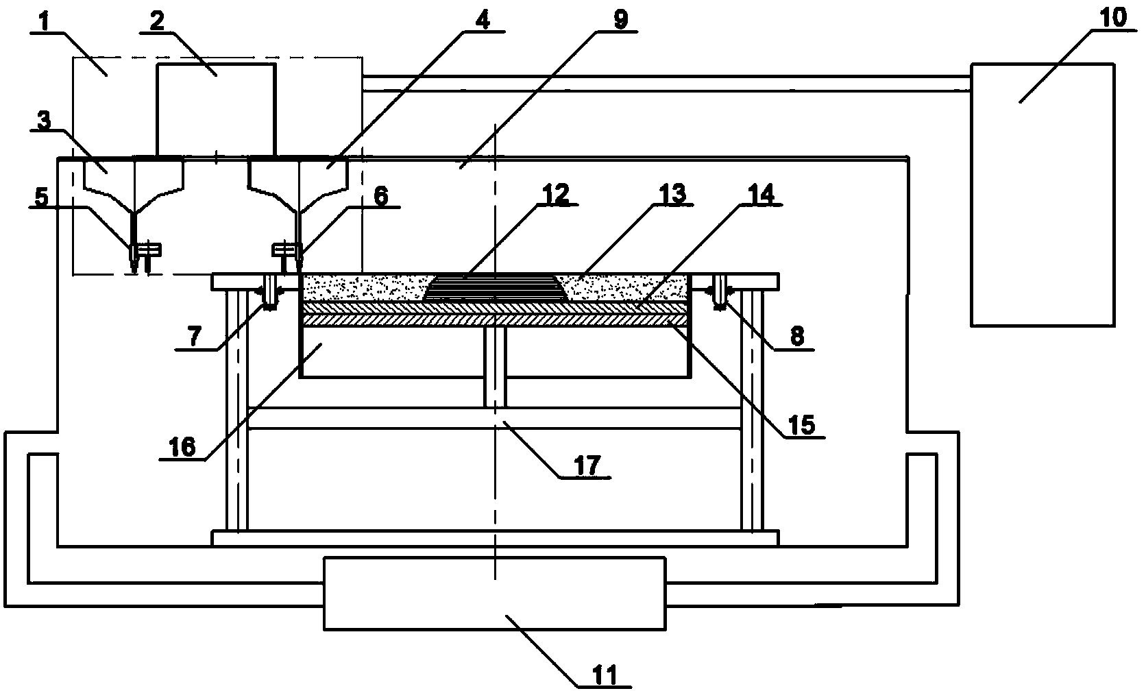
[0039] Such as figure 1 As shown, the first embodiment of the high-energy beam additive manufacturing equipment involved in the present invention includes a powder supply and scanning module 1 , a working chamber 9 , a workbench, a control system 10 and a gas purification module 11 .

[0040] The control system 10 calculates the processing trajectory and generates relevant numerical control signals, which are used to regulate the powder supply connected to the control system 10 and the cooperative work of the scanning module 1 , the workbench and the gas purification module 11 . To simplify the graph, figure 1 Only the connection between the powder supply and the scanning module 1 and the control system 10 is shown in the figure, and the connections between the other components and the control system 10 are not shown. It should be noted that this connection may include contact connections such as physical lines, or non-contact connections such as electronic signals.

[0041]...

Embodiment 2

[0056] On the basis of the first specific implementation of the high-energy beam additive manufacturing equipment involved in the present invention, the second specific implementation of the high-energy beam additive manufacturing equipment involved in the present invention can be obtained, such as Figure 4 shown. In this embodiment, the powder supply and scanning module 1 is still composed of a scanning galvanometer group 2, a first powder storage hopper 3, a second powder storage hopper 4, a first one-way powder spreader 5, and a second one-way powder spreader 6 The composition, powder supply and arrangement of components inside the scanning module 1 are also consistent with the first embodiment of the high energy beam additive manufacturing equipment. The difference is that the scanning galvanometer group 2, the first powder storage hopper 3, the second powder storage hopper 4, the first one-way powder spreader 5, and the second one-way powder spreader 6 are respectively f...

Embodiment approach

[0069] exist figure 1 On the basis of the shown equipment, the first one-way powder spreader 5 and the second one-way powder spreader 6 are removed, and a two-way powder spreader 30 is added to form the high-energy beam additive manufacturing large-scale metal parts involved in the present invention The third specific implementation of , such as Figure 5 shown.

[0070] The workbench is still composed of the first powder recovery cylinder 7 , the second powder recovery cylinder 8 and the forming cylinder 16 , and remains stationary inside the working chamber 9 . It should be noted that the "stationary" state defined here refers to the absolute stillness of the components inside the workbench along the powder spreading direction. The first powder recovery cylinder 7 and the second powder recovery cylinder 8 are still located on both sides of the forming cylinder 16 respectively. The upper surfaces of the first powder recovery cylinder 7, the second powder recovery cylinder ...


PUM


Abstract

The invention discloses equipment for manufacturing a large-size metal part in a high energy beam additive manufacturing mode and a control method of the equipment. The equipment comprises a work cavity, a worktable, a control system, a high energy beam scanning generator, a powder storage hopper, a powder laying device and a gas purification module, wherein the worktable is composed of a forming cylinder and a powder recycling cylinder, and the upper surface of the forming cylinder and the upper surface of the powder recycling cylinder are coplanar and form a work plane. The control system controls the high energy beam scanning generator and the powder laying device to move opposite to the worktable in the powder laying direction. The equipment for manufacturing the large-size metal part in the high energy beam additive manufacturing mode and the control method of the equipment largely shorten the waiting time caused by pre-installation of a powder bed when a common laser/electron beam selective melting technology is used for processing a part, thereby obviously improving the forming efficiency of high energy beam additive manufacturing. Through the application of the equipment for manufacturing the large-size metal part in the high energy beam additive manufacturing mode and the control method of the equipment, a metal part with a meter-grade size, high performance, high accuracy and a complex structure can be manufactured efficiently and rapidly.

Description

technical field [0001] The invention belongs to the technical field of high-energy beam processing, and in particular relates to equipment and a control method for high-energy beam additive manufacturing of large-sized metal parts. The invention is an additive manufacturing technology based on the synchronous movement of a high-energy beam scanning generator and a powder spreader, and is especially suitable for high-efficiency forming of large-scale, high-performance, high-precision and complex-structure metal parts. Background technique [0002] Additive manufacturing technology, also known as three-dimensional printing technology (3D-Printing), is an emerging manufacturing technology. Different from traditional equal-material manufacturing (casting, forging, welding) and subtractive manufacturing (machining), additive manufacturing technology is based on the discrete-accumulation rule, and according to the three-dimensional data of the parts, the materials are connected in...

Claims


Application Information

Patent Timeline
Patent Type & Authority Applications(China)
IPC IPC(8): B22F3/105
CPCY02P10/25
Inventor 曾晓雁魏恺文王泽敏王福德朱海红李祥友蒋明
Owner TECH LASER TECH SHANGHAI CO LTD
Why Eureka
Try Eureka