Cable force detecting method and cable force sensor using same

A technology of cable force sensor and detection method, which is applied to force/torque/power measuring instruments, instruments, measuring devices, etc., can solve the problems of complex sensor processing technology, low sensor measurement accuracy, slow sensor response speed, etc., and achieve test Fast speed, improve the signal-to-noise ratio, and eliminate the effect of mutual influence

Active Publication Date: 2014-08-27
NINGBO UNIV +1
View PDF4 Cites 11 Cited by
  • Summary
  • Abstract
  • Description
  • Claims
  • Application Information

AI Technical Summary

Problems solved by technology

However, the existing magnetoelastic effect method has the following problems: 1. The magnetic flux sensor generates an induced electromotive force through the change of the magnetic flux inside the detection coil induction coil skeleton. interference, resulting in low measurement accuracy of the sensor; 2. During the measurement process, the steel cable must first be magnetized by the excitation coil, and then the change of the magnetic flux of the magnetic field when the steel cable is deformed is induced by the detection coil, and then the cable force is calculated and measured. It takes a certain response time to magnetize the steel cable, and it also takes a certain time for the detection coil to obtain the magnetic field information of the measured characteristic signal, which leads to a slow response speed of the sensor and a slow test speed; The possible large and evenly distributed magnetic flux requires strict size matching between the detection coil and the coil bobbin and between the detection coil and the excitation coil, which leads to a relatively complicated sensor processing technology and a signal-to-noise ratio of the sensor during the measurement process. Low

Method used


Image

  • Cable force detecting method and cable force sensor using same
  • Cable force detecting method and cable force sensor using same
  • Cable force detecting method and cable force sensor using same

Examples


Embodiment 1

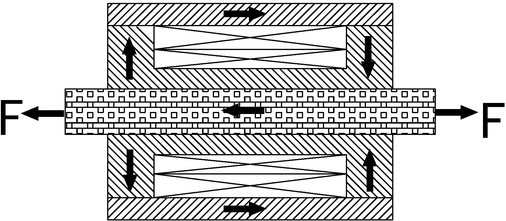
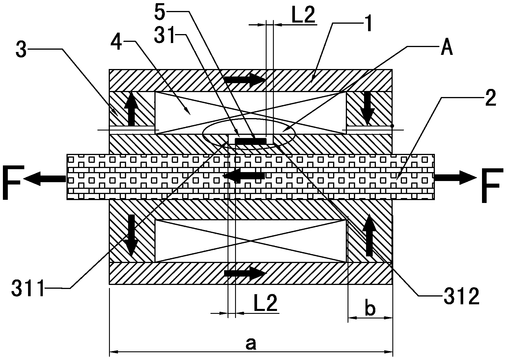
[0067] Embodiment one: if Figure 1~4 As shown, a cable force sensor includes a housing 1, a coil frame 3 sleeved on a steel cable 2, and an excitation coil 4. The excitation coil 4 is formed by winding a copper wire on the outer wall of the coil frame 3. The coil The outer wall of the skeleton 3 is provided with a rectangular groove 31, the rectangular groove 31 is located in the middle of the axial direction F of the coil bobbin 3, and the magnetoelectric sensing unit 5 with magnetostrictive performance is installed in the rectangular groove 31. The sensing unit 5 is a cuboid structure, the magnetization direction of the magnetoelectric sensing unit 5 is parallel to the axial direction of the bobbin 3, the upper end surface of the magnetoelectric sensing unit 5 does not exceed the rectangular groove 31, and the long side of the magnetoelectric sensing unit 5 Parallel to the axial direction of the coil bobbin 3, the two ends 51 and 52 of the magnetoelectric sensing unit 5 alo...

Embodiment 2

[0072] Embodiment 2: This embodiment is basically the same as Embodiment 1, the only difference is that the sum of the volumes of the first magnetostrictive layer 53 and the second magnetostrictive layer 55 in this embodiment accounts for the volume of the first magnetostrictive layer 53, the pressure 76% of the volume sum of the transistor layer 54 and the second magnetostrictive layer 55 .

Embodiment 3

[0073] Embodiment three: as Figure 1~4 As shown, a cable force sensor includes a housing 1, a coil frame 3 and an excitation coil 4 sleeved on a steel cable 2, and the excitation coil 4 is formed by winding a copper wire on the outer wall of the coil frame 3. The coil The outer wall of the skeleton 3 is provided with a rectangular groove 31, the rectangular groove 31 is located in the axial F middle of the coil bobbin 3, and the magnetoelectric sensing unit 5 with magnetostrictive performance is installed in the rectangular groove 31, and the magnetoelectric sensor unit 5 is installed in the rectangular groove 31. The sensing unit 5 is a cuboid structure, the magnetization direction of the magnetoelectric sensing unit 5 is parallel to the axial direction of the bobbin 3, the upper end surface of the magnetoelectric sensing unit 5 does not exceed the rectangular groove 31, and the long side of the magnetoelectric sensing unit 5 Parallel to the axial direction of the coil bobbi...


PUM

PropertyMeasurementUnit
thicknessaaaaaaaaaa
thicknessaaaaaaaaaa
thicknessaaaaaaaaaa

Abstract

The invention discloses a cable force detecting method and a cable force sensor using the same. A linear relationship between induction voltage and steel cable force is decided, the induction voltage is generated by a magnetic-electric sensing unit in the cable force sensor along with the change of the magnetic field, and the magnetic-electric sensing unit with magnetostriction performance is utilized to replace a detecting coil of a magnetic flux senor as a detecting unit to detect the induction voltage of the cable force sensor in axial deformation of a steel cable. The cable force detecting method has the advantages of reducing magnetic flux leakage of the detecting unit and magnetic flux leakage between the detecting unit and an excitation coil and improving the measurement accuracy of the sensor. In addition, the magnetic-electric sensing unit with the magnetostriction performance can directly respond the induction voltage through change of the internal magnetic field of a coil framework, and a method of responding the induction voltage through the change of the magnetic flux and then transmitting the induction voltage through the detecting unit to obtain response voltage is avoided. Thus, the response time is short, and the testing speed is high. Furthermore, the cable force sensor is simple in manufacturing procedure, and the signal to noise ratio of the sensor is improved.

Description

technical field [0001] The invention relates to a steel cable force detection technology, in particular to a cable force detection method and a cable force sensor using the method. Background technique [0002] The steel cable is a kind of flexible load-bearing component, and its cable force state is an important symbol to measure whether the building is in normal operation state. Real-time monitoring of the cable force of the steel cable is of great engineering significance for building health monitoring. The magnetoelastic effect method is currently the most potential method for monitoring the cable force. This method uses the magnetic flux sensor to measure the change of the magnetic flux in the steel cable, so as to obtain the cable force of the steel cable. The specific process is as follows: figure 1 As shown in the magnetic flux sensor, the magnetic flux sensor includes a coil bobbin, a detection coil wound on the outer surface of the coil bobbin, an excitation coil w...

Claims


Application Information

Patent Timeline
Patent Type & Authority Applications(China)
IPC IPC(8): G01L5/00
Inventor 冯志敏李宏伟邵磊胡海刚李秋胜李玲张刚陈郭赵洪洋汪明
Owner NINGBO UNIV
Why Eureka
Try Eureka