
A closed-loop control test method for converter subunits under full operating conditions

A technology of closed-loop control and test method, which is applied in the field of power electronics and can solve problems such as waste of electric energy

Active Publication Date: 2016-08-31
STATE GRID CORP OF CHINA +1
View PDF8 Cites 0 Cited by
  • Summary
  • Abstract
  • Description
  • Claims
  • Application Information

AI Technical Summary

Problems solved by technology

[0003] At present, the experimental method usually used in the single converter test is to connect a diode rectifier circuit on the DC side of the converter to be tested to provide a stable DC voltage for the converter. At this time, the converter is working in the inverter state; the load side is connected to Inductive loads such as motors, but using the motor as a load will absorb the active power of the grid, resulting in a waste of electric energy

Method used

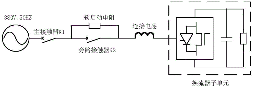
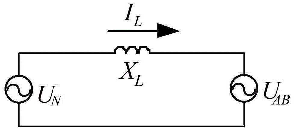

Image

  • A closed-loop control test method for converter subunits under full operating conditions
  • A closed-loop control test method for converter subunits under full operating conditions
  • A closed-loop control test method for converter subunits under full operating conditions

Examples


Embodiment Construction

[0045] The present invention will be described in further detail below in conjunction with the accompanying drawings.

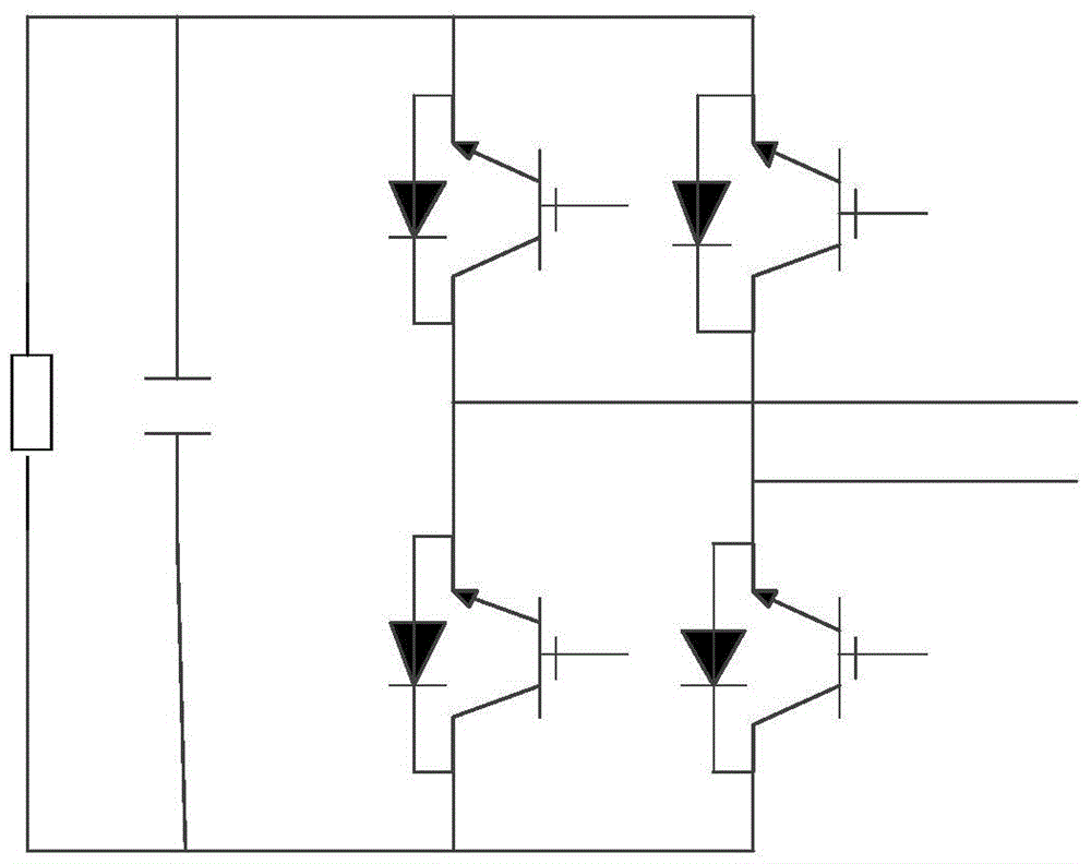
[0046] The chain-link converter is formed by cascading several identical converter subunits. Among them, the cascaded subunits adopt no differentiation configuration, and each converter subunit adopts H-bridge topology, followed by DC capacitors and Voltage grading resistors, the main wiring diagram of which is given by figure 1 shown. Each unit is equipped with an intelligent unit controller, whose functions include subunit data sampling, logic control and subunit level protection. In the chain topology, the working voltage of the power electronic devices in the converter subunit is effectively clamped at the voltage of the DC capacitor, which avoids the problem of series connection of power electronic devices. The voltage level greatly simplifies the high voltage converter design.

[0047] The present invention provides a closed-loop control test method ...


PUM


Abstract

The invention provides a test method for transverter subunit full working condition closed-loop control. The test method includes the following steps of calculating current of a connecting inductor; calculating an active component and a reactive component of the current of the connecting inductor; calculating voltage of the connecting inductor and voltage of the alternating-current end of a transverter subunit; calculating an active component reference value and a reactive component reference value of the current of the connecting inductor; adopting a PI adjustor for adjusting voltage across the two ends of the transverter subunit. According to the test method for transverter subunit full working condition closed-loop control, tests of the actual working condition of the chained transverter subunit are simulated, and the multiple tests such as a main circuit test, an energy-obtaining loop test, a sampling loop test and a unit controller function test can be achieved through one test process, so that the test flow is simplified, electric energy loss can be saved, and cost of tests in batches is reduced.

Description

technical field [0001] The invention belongs to the technical field of power electronics, and in particular relates to a closed-loop control test method for a converter subunit under full working conditions. Background technique [0002] Chain-link converters, which are widely used in high-power power electronic devices, are formed by cascading several identical converter subunits. Among them, the cascaded sub-units adopt a non-differentiated configuration, and each sub-unit adopts an H-bridge topology. In the chain topology, the working voltage of the power electronic devices in the converter unit is effectively clamped at the voltage of the DC capacitor, which avoids the problem of series connection of power electronic devices. At the same time, the voltage of the entire power electronic device can be increased by increasing the number of cascaded units. level, which greatly simplifies the design of high-voltage converters. As the core part of the main circuit of the rea...

Claims


Application Information

Patent Timeline
Patent Type & Authority Patents(China)
IPC IPC(8): G01R31/40
Inventor 周娜宗波乔尔敏蔡博康伟雷晰
Owner STATE GRID CORP OF CHINA
Learn More