Automatic riveting device for windscreen wiper framework and application method of automatic riveting device
A wiper and skeleton technology is applied in the field of automatic riveting equipment for wiper skeletons. Effect
- Summary
- Abstract
- Description
- Claims
- Application Information
AI Technical Summary
Problems solved by technology
Method used
Image

Examples
Embodiment 1
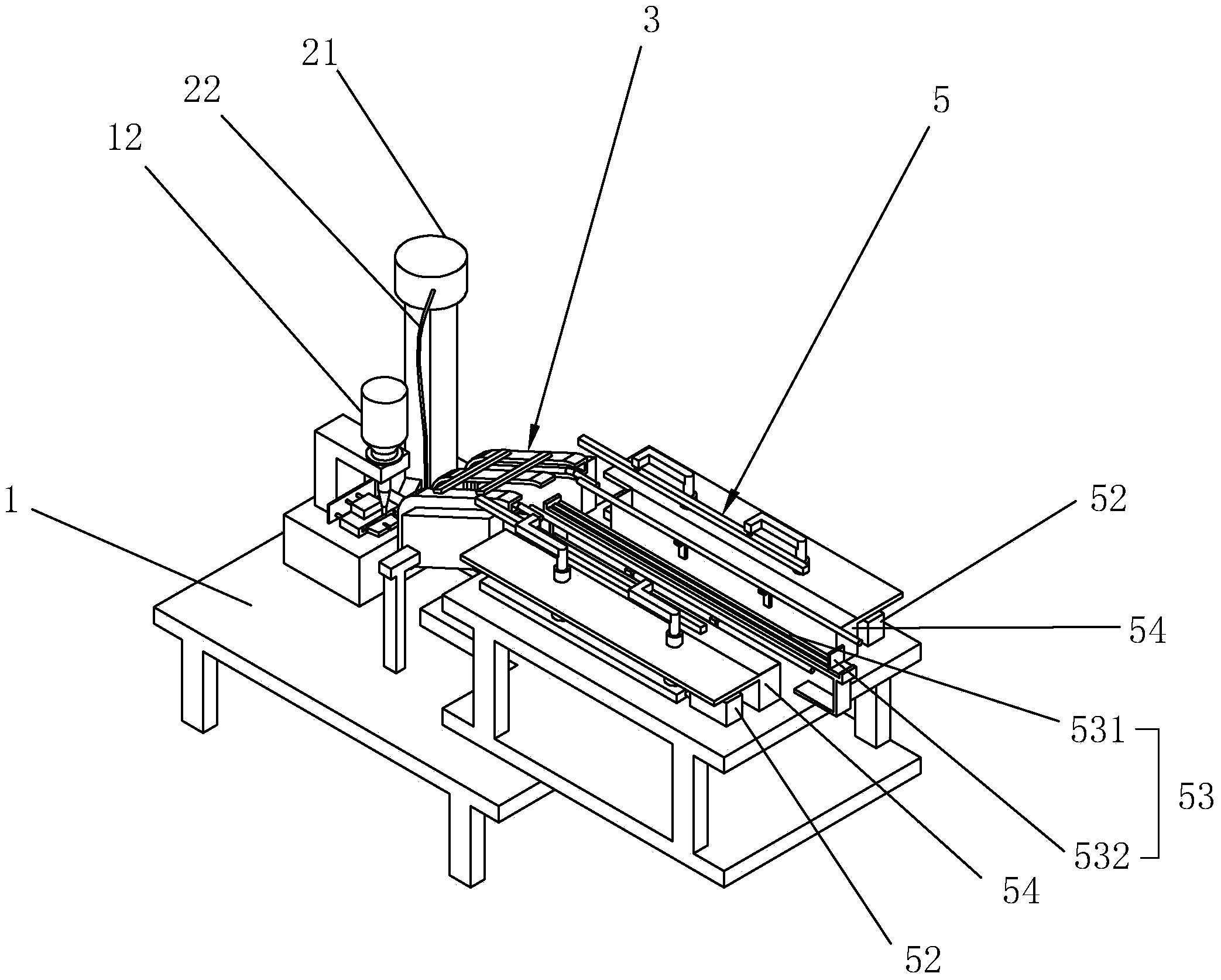
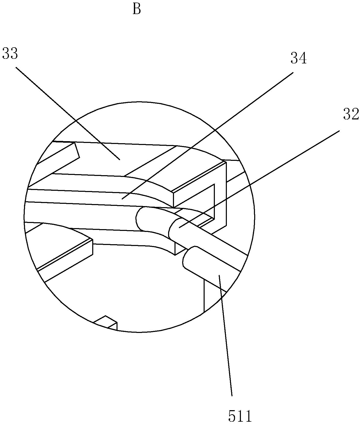
[0055] like Figure 1 to Figure 8 As shown, the wiper skeleton automatic rivet equipment has a workbench 1, a rivet supply device 2, a horizontal slide rail swing device 5, and a feeding device, wherein the feeding device consists of a feeding slide rail device 3, a feeding manipulator device 4, and a second pushing device 53 Composition (It should be noted here that the number of the second pushing device is 53, which does not mean that the second pushing device 53 is a component of the horizontal slide rail swing device 5).
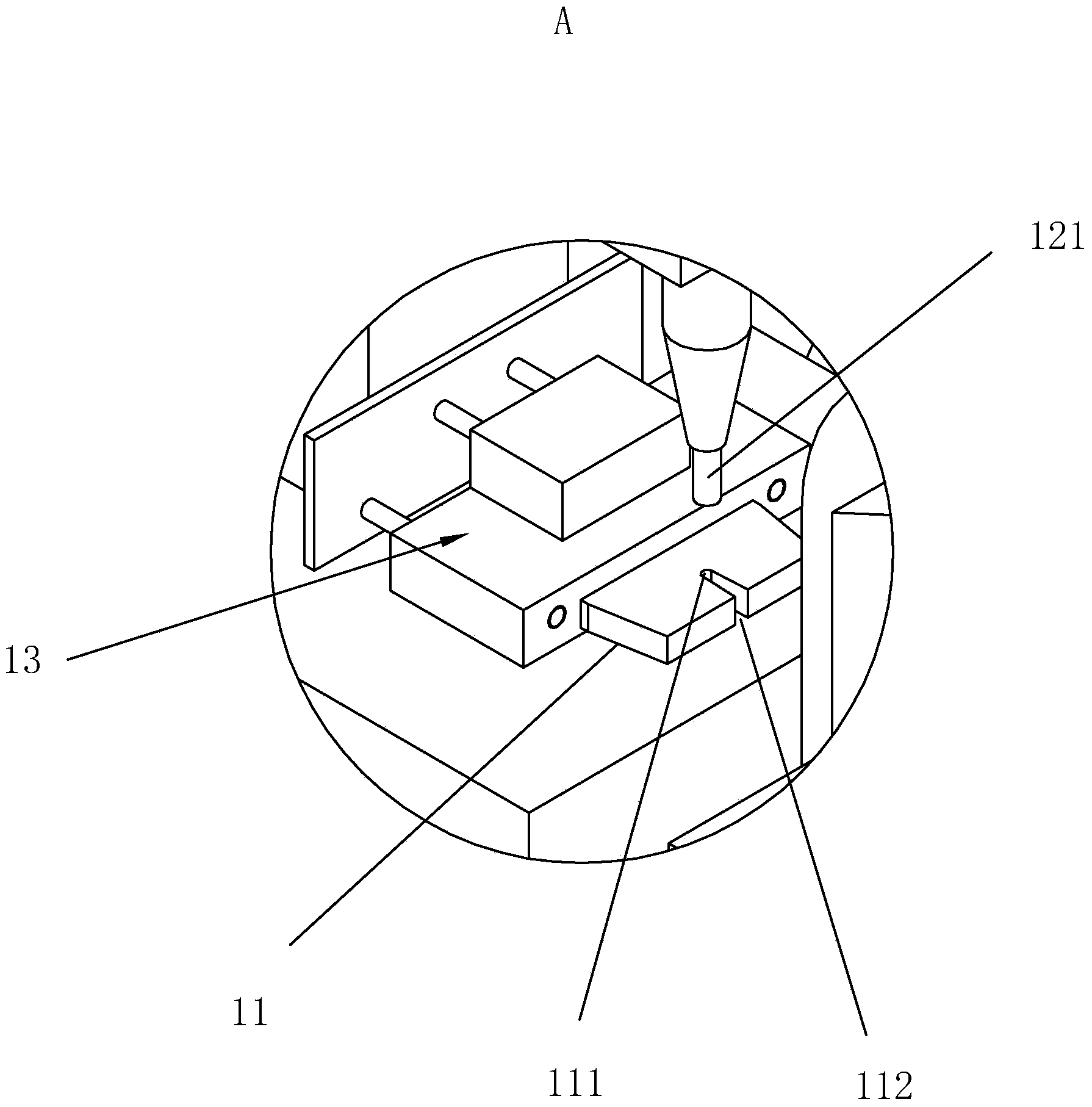
[0056] Wherein, the workbench 1 is provided with a riveting seat 11 for placing the wiper frame 91 to be processed, and the workbench 1 is provided with a riveting machine 12 capable of riveting the wiper frame 91 to be processed, and the riveting seat 11 is A rivet hole 111 is provided on the rivet hole 111, and a notch 112 is provided on the rivet hole 111. The notch 112 faces the insertion direction of the wiper frame 91 to be processed. The size of ...
Embodiment 2
[0068] like Figure 9 to Figure 14 As shown, embodiment 2 is to increase the conveying device 6 and the infrared detection device 7 on the embodiment 1, and the conveying device 6 and the infrared detection device 7 can continuously supply the horizontal slide rail swing device 5 wiper skeleton group 9;
[0069] The transport device 6 is located on one side of the horizontal slide rail swing device 5, and is used to transport the wiper skeleton group 9 to the horizontal slide rail swing device 5. The transport device 6 includes a rotating device 61, a lifting device 62, a telescopic pick-up device 63, and a rotating device 61 includes a bracket 611, two turntables 612 facing up and down on the bracket 611, and a rotating shaft 613 fixed between the two turntables 612. The bracket 611 is connected to the workbench 1, the lifting device 62 is fixed on the rotating shaft, and the telescopic pick-up device 63 is fixed. On the lifting device 62, the telescopic pick-up device 63 inc...
Embodiment 3
[0072] like Figure 15 As shown, embodiment 3 adds a collecting device 10 on the basis of embodiment 2. The collecting device 10 includes a conveyor belt device 101 and a collecting frame 102. There is a blanking hole 14 that runs through the upper and lower surfaces of the workbench 1. A blanking baffle 15 is arranged on the other side of the blanking hole relative to the riveting seat. The height of the blanking baffle 15 should be lower than the height of the riveting seat 11, and it cannot Block the action of the manipulator on the feeding manipulator device 4 sending the wiper skeleton 91 to the riveting seat 11. After the riveting machine 12 completes the riveting of the wiper skeleton 91, the first pushing device 13 pushes the wiper skeleton 91 out, passes through the blanking hole 14 and falls on the conveyor belt device 101, and the conveyor belt device 101 can send these wiper skeletons 91 to the collection frame 102 inside.
[0073] The wiper automatic riveting eq...
PUM
 Abstract
Description
Claims
Application Information
 - Generate Ideas
- Intellectual Property
- Life Sciences
- Materials
- Tech Scout
- Unparalleled Data Quality
- Higher Quality Content
- 60% Fewer Hallucinations
Browse by: Latest US Patents, China's latest patents, Technical Efficacy Thesaurus, Application Domain, Technology Topic, Popular Technical Reports.
© 2025 PatSnap. All rights reserved.Legal|Privacy policy|Modern Slavery Act Transparency Statement|Sitemap|About US| Contact US: help@patsnap.com