L-shaped multifunctional oil press and work method

A hydraulic press, multi-functional technology, applied in the direction of stamping machines, presses, manufacturing tools, etc., can solve the problems that die forgings cannot be processed, single-shaped products, etc., and achieve strong anti-eccentric load capability, high positioning accuracy, and guiding performance Good results

Inactive Publication Date: 2014-09-03
CHANGSHA LEIFENG HEAVY FORGING
View PDF7 Cites 3 Cited by
  • Summary
  • Abstract
  • Description
  • Claims
  • Application Information

AI Technical Summary

Problems solved by technology

Although this patent is not limited by the size and length of the workpiece, it also has the defect that it can only process products of a single shape, such as connecting rods, pistons of hydraulic parts, steps and mushroom-type die forgings cannot be processed

Method used


Image

  • L-shaped multifunctional oil press and work method
  • L-shaped multifunctional oil press and work method

Examples


Embodiment 1

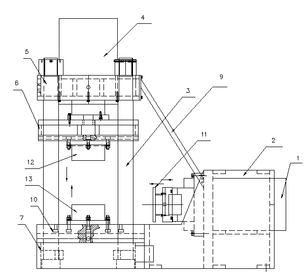
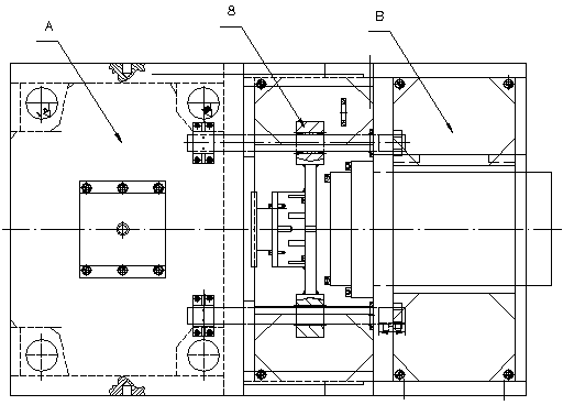
[0020] Example 1, such as figure 1 , figure 2 The L-shaped multifunctional hydraulic press shown is composed of a vertical hydraulic press A and a horizontal hydraulic press B, wherein the horizontal hydraulic press B includes: a horizontal hydraulic press cylinder assembly 1; a horizontal hydraulic press frame 2; a horizontal hydraulic press Hydraulic right mold 11; horizontal hydraulic press guide mechanism 8; wherein, the horizontal hydraulic press cylinder assembly 1 is placed on the upper part of the horizontal hydraulic press frame 2, and the horizontal hydraulic right mold 11 is movably connected to the horizontal hydraulic press guide mechanism 8; Described vertical hydraulic machine is by four columns 3; Vertical hydraulic machine cylinder assembly 4; Vertical hydraulic machine upper beam 5; Slider 6; Workbench 7; Placed on the upper part of the upper beam 5 of the vertical hydraulic press, the slider 6 is movably connected with the four columns 3, the upper mold 12...

Embodiment 2

[0021] Embodiment 2, the structure is the same as that of Embodiment 1, a working method of an L-shaped multifunctional hydraulic press: when processing piston workpieces, in the first step, the vertical hydraulic press A works, and the upper mold 12 moves vertically downwards, and is combined with the lower mold 13 The mold completes the positioning, clamping, and forming of the left end of the piston workpiece; the second step, the horizontal hydraulic press B drives the right mold 11 to move horizontally from right to left, and molds with the right end of the upper and lower molds of the vertical hydraulic press to complete the overall molding of the piston workpiece; third In the first step, the horizontal hydraulic press B drives the right mold 11 to eject from left to right; in the fourth step, the vertical hydraulic press A drives the upper mold 12 to eject from the bottom to the top to complete the integral precision forging of the product piston. The left end face of t...

Embodiment 3

[0022] Embodiment 3, the workpiece of Embodiment 2 is replaced with a bearing. When the hydraulic press is working, the first step is to work the vertical hydraulic press. The hydraulic automatic control system controls and drives the upper mold to move vertically downwards, and molds with the lower mold to complete positioning, Clamping and workpiece forming; the second step, the vertical hydraulic press A drives the upper mold 12 to move from bottom to top to eject. Through the above two steps, the forming of ordinary workpieces is completed.


PUM


Abstract

The invention relates to an L-shaped multifunctional oil press and a work method, and relates to the field of presses. According to the technical scheme, an L shape is formed by a vertical oil press body (A) and a horizontal oil press body (B), and the vertical oil press body and the horizontal oil press body are controlled by a hydraulic control system. The L-shaped multifunctional oil press is characterized in that the vertical oil press body and the horizontal oil press body are connected through a reinforcing rib (9), one end of the reinforcing rib (9) is connected with an upper beam of the vertical oil press body, and the other end of the reinforcing rib (9) is connected with the upper portion of a rack of the horizontal oil press body; the right end of a workbench of the vertical oil press body is movably connected with the mold end of the horizontal oil press body to form a frame closed structure. In the working process, a right mold arranged on the left end face of the horizontal oil press body is adopted as a left mold when an upper mold and a lower mold of the vertical oil press body are combined, and products of different types, such as connecting rod types, mushroom types, step types and piston types, can be produced through the function of the upper mold, the lower mold, the right mold and the left mold.

Description

technical field [0001] The invention relates to the field of presses, in particular to thermal processing equipment for oil presses. Background technique [0002] The hydraulic press is a kind of special hydraulic oil as the working medium and the hydraulic pump of the hydraulic station as the power source. The hydraulic oil is under the force of the pump; it enters the hydraulic cylinder through the hydraulic pipeline, pressure control valve, flow control valve, and direction control valve. Convert hydraulic energy into mechanical energy. Through the mechanical, electrical and hydraulic control system, the hydraulic oil circulates in the hydraulic system, so that the piston moves in a reciprocating and linear motion repeatedly, so as to meet the technological requirements of the product. Hydraulic presses are classified according to their structural forms and can be divided into four-column hydraulic presses, single-column hydraulic presses, horizontal hydraulic presses, a...

Claims


Application Information

Patent Timeline
Patent Type & Authority Applications(China)
IPC IPC(8): B30B1/32B30B15/00B30B15/04
Inventor 杨重科赵永楚张宇
Owner CHANGSHA LEIFENG HEAVY FORGING
Why Eureka
Try Eureka