Self-control type energy-efficient heat tracing system

A high-efficiency energy-saving, control system technology, applied in pipeline systems, mechanical equipment, gas/liquid distribution and storage, etc., can solve problems such as energy waste, water consumption, etc., to reduce water consumption, reduce energy waste, The effect of saving energy consumption

Active Publication Date: 2014-09-03
PETROCHINA CO LTD
View PDF7 Cites 3 Cited by
  • Summary
  • Abstract
  • Description
  • Claims
  • Application Information

AI Technical Summary

Problems solved by technology

However, in the normal production process, the temperature of the medium in the material pipeline of most buried steam tracing pipelines is much higher than its freezing point so as not to lose fluidity, such as atmospheric residual oil, vacuum residual oil, vacuum wax Oil, etc.; the temperature of the medium in the pipeline or pipe section of some oil refining and chemical equipment or petroleum storage and transportation system is even higher than the temperature of the heating steam, such as catalytic cycle oil slurry, etc., making the heating steam become a cold medium for heat extraction, continuously The use of steam results in waste of energy and consumption of water resources

Method used


Image

  • Self-control type energy-efficient heat tracing system
  • Self-control type energy-efficient heat tracing system

Examples


Embodiment 1

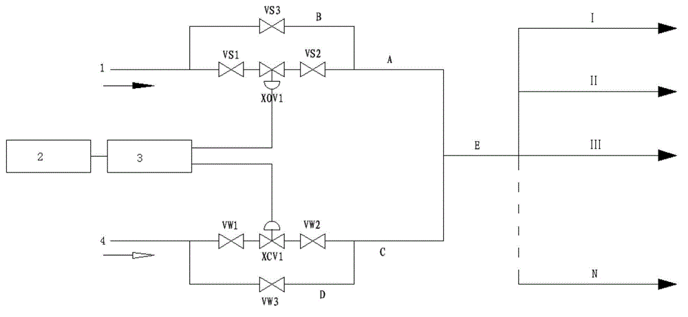
[0061] see figure 1 As shown, the control system set in the steam heating system in the embodiment of the present invention is the total steam source control type, at least including: the heating steam cut-off valve XOV1, the front hand valve Vs1 of the heating steam cut-off valve, the heating steam cut-off valve The rear hand valve Vs2 of the heating steam cut-off valve, the auxiliary line valve Vs3 of the heating steam cut-off valve, the blowing air cut-off valve XCV1, the front hand valve Vw1 of the blown wind cut-off valve, the back hand valve Vw2 of the blown wind cut-off valve, and the blown wind cut-off valve The auxiliary line valve Vw3 of the valve, the main heating steam circuit A, the heating steam circuit B, the main sweeping air circuit C, the sweeping air circuit D, the total steam source summary pipeline E, the first heating pipeline I, the second Two heating pipelines II, the third heating pipeline III, the Nth heating pipeline N, heating steam inlet 1, oil ref...

Embodiment 2

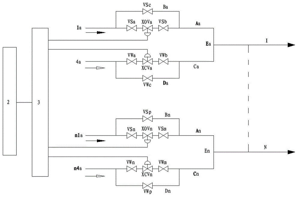
[0069] see figure 2 As shown, the control system set in the steam heat tracing system in the embodiment of the present invention is the steam source control type, at least including: the first traced steam cut-off valve XOVa, the front hand valve Vsa of the first traced steam cut-off valve , the back valve Vsb of the first heating steam cut-off valve, the auxiliary line valve Vsc of the first heating steam cut-off valve, the first blowing air cut-off valve XCVa, the front hand of the first blowing air cut-off valve Valve Vwa, the back valve Vwb of the first blowing air cut-off valve, the auxiliary line valve Vwc of the first blowing air cut-off valve, the Nth heating steam cut-off valve XOVn, the Nth heating steam cut-off valve The front hand valve Vsn, the back valve Vsm of the Nth heating steam cut-off valve, the auxiliary line valve Vsp of the Nth heating steam cut-off valve, the Nth purge air cutoff valve XCVn, the Nth purge air cutoff valve The front hand valve Vwn of t...


PUM


Abstract

The invention discloses a self-control type energy-efficient heat tracing system and belongs to the fields of petroleum refining, petrochemical engineering and petroleum storage and transport. According to the heat tracing system, steam serves as a heat tracing medium. A control system is arranged in a steam heat tracing system. The self-control type energy-efficient heat tracing system comprises the steam heat tracing system and a blowing and sweeping air system. The blowing and sweeping air system and the steam heat tracing system are interlocked through a control unit when a petroleum refining and chemical engineering device or a petroleum storage and transport system is operated, so that servo operation of use/cutting of the steam heat tracing system and the operation state/shut-down state of the petroleum refining and chemical engineering device or the petroleum storage and transport system is achieved. An existing continuous inflow steam heat tracing mode is improved into a self-control intermittent feeding type steam heat tracing mode, system operation is good, intelligent control over the steam heat tracing system in the operation state of the petroleum refining and chemical engineering device or the petroleum storage and transport system is achieved, steam is reasonably and intermittently used, it is guaranteed that the temperature of the medium is lower than the temperature of the heat tracing steam, and waste of energy and consumption of water resources are effectively reduced.

Description

technical field [0001] The invention relates to the fields of petroleum refining, petrochemical industry and petroleum storage and transportation, in particular to a self-controlled high-efficiency energy-saving heat tracing system. Background technique [0002] In production practice, some condensable media, such as crude oil and heavy oil, may even solidify and affect production due to the gradual decrease in temperature and increase in viscosity during pipeline transportation. Therefore, when transporting this kind of medium, insulation measures must be taken, such as adding steam and other accompanying pipes near the material pipeline to maintain a certain temperature of the material. Wrapping steam pipes or hot water pipes and oil pipes in the same insulation shell is called heat tracing. [0003] In cold areas or devices with high freezing point oil or other fluid materials, steam tracing pipes are usually buried in the heat-insulated pipes, and steam at 0.3MPa ~ 1.0M...

Claims


Application Information

Patent Timeline
Patent Type & Authority Applications(China)
IPC IPC(8): F17D1/06F17D1/18F17D3/01
Inventor 张英张东明刘宇王强苗兴东张华倪喜明
Owner PETROCHINA CO LTD
Why Eureka
Try Eureka