Whirlwind type heat radiation LED lamp

A technology of LED lamps and LED lamps, applied in lighting and heating equipment, cooling/heating devices of lighting devices, lighting devices, etc., can solve the problems of bulky heat dissipation devices, speed up the flow of gas in the heat conduction sheet, etc., and reduce maintenance costs , Replacement and maintenance are light and convenient, and the method is ingenious

Active Publication Date: 2014-09-03
潘忠勋
View PDF4 Cites 6 Cited by
  • Summary
  • Abstract
  • Description
  • Claims
  • Application Information

AI Technical Summary

Problems solved by technology

[0004] The key point of the present invention is to solve the heat dissipation problem of the existing LED lamps. It utilizes the physical phenomenon in combustion to produce a rotation superposition effect, so that as long as a slight active convection is given, the flow speed of the gas in the heat conduction sheet will be greatly accelerated to achieve heat dissipation. Effect, through intelligent control, save energy and prolong the life of the setting structure, the method is ingenious, simple and scientific
[0005] The second purpose of the present invention is: in order to solve the bulky heat dissipation device in the existing high-power LED lamp and indoor and outdoor lighting, a large number of aluminum alloy materials are used, and the production of these metal materials is not worth the candle with low carbon, energy saving, and environmental protection.

Method used


Image

  • Whirlwind type heat radiation LED lamp
  • Whirlwind type heat radiation LED lamp
  • Whirlwind type heat radiation LED lamp

Examples


Embodiment Construction

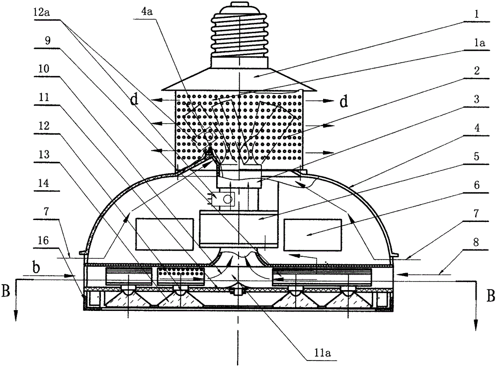
[0030] In order to further understand structure of the present invention, describe as follows with reference to accompanying drawing:

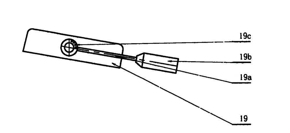
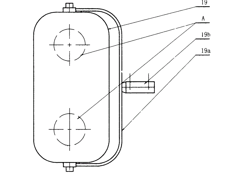
[0031] refer to figure 1 , 2 This whirlwind heat dissipation LED lamp is mainly composed of a heat conduction sheet 9 and an LED lamp 12, and is characterized in that its heat conduction sheet 9 is a conduction sheet 9 device mounted on an LED bulb lamp or an LED array chip 12a, and the heat conduction sheet 9 is shaped like; there are several vertical strips and elongated pieces on a horizontal piece, and there is no horizontal connecting piece in the straight piece made by different processes, which can make the air flow unimpeded. The heat dissipation hole group 9a, the heat conduction sheet 9 and the LED chip lamp 12 are fixed in the middle hole of the supporting plate seat 15, and the upper part of the heat conduction sheet 9 has a """-shaped long and narrow air duct taking into account heat preservation and protection. ""-shaped seat co...


PUM


Abstract

Previously, the heat radiation problem of a high-power LED chip is the focus of a technology. A convection mode is mostly adopted, the upper portions of LED lamps are respectively provided with a large cooling fin made of aluminum alloy in a pressure casting mode, the structure is heavy, replacement and maintenance are inconvenient, most of the cooling fins cannot achieve the cooling effect when temperature is high, light attenuation is accelerated, and the service life of the LED lamps is shortened. A whirlwind type heat radiation LED lamp is mainly composed of heat conducting fins, an LED lamp body and LED patches, the physical phenomenon in hydromechanics is utilized, a plurality of air channels within a circumference are divided into the vortex effect which has an angle and generates rotary superposition under the action of a fan, slight fan active convection is utilized, the flowing speed of gas in the narrow heat conducting fin air channels is greatly improved, the super-strong heat radiation effect is achieved, the temperature of an LED chip is greatly reduced, light attenuation is greatly reduced, the service life of the LED lamp body is prolonged, indoor and outdoor lighting lamps and luminaires for industrial use can be replaced easily through a built-in driver, the LED lamp is as light, convenient to operate and fast as a common bulb, intelligent control is utilized, the two are combined alternately, energy is saved, the structural life of the lamp is prolonged, and the method is ingenious, simple and scientific.

Description

technical field [0001] The invention belongs to LED lighting industry Background technique [0002] In the previous high-power LED lighting, lamps, and chip heat dissipation, it was a technical focus. If the heat dissipation is not good, it will directly affect the life of the LED. If it is light, it will accelerate the light decay and shorten the life of the LED lamp, and if it is serious, it will burn the chip and LED bulb. Therefore, there is a large aluminum alloy die-cast heat sink on the upper part of the LED lamp, which uses air convection to reduce the temperature. The greater the power of the LED, the larger the heat dissipation "hat", so the heat from the heat sink at the bottom of the chip is dissipated in the form of convection of the heat sink area, so especially the bulky heat dissipation "hat" on the LED street lamp It is to use the size of the heat sink area of ​​the aluminum alloy, and the temperature of the surrounding environment will rise after the heat ...

Claims


Application Information

Patent Timeline
Patent Type & Authority Applications(China)
IPC IPC(8): F21S2/00F21V29/02F21Y101/02F21K9/23F21Y115/10
Inventor 潘忠勋潘战海潘战宇
Owner 潘忠勋
Why Eureka
Try Eureka