Low-condensing-pressure deep supercooling efficient dehumidifier

A technology of condensing pressure and deep subcooling, which is applied to compressors, refrigerators, compressors, etc. with multiple condensers. Compressor power consumption increases and other problems, to achieve the effect of improving evaporation heat absorption capacity and dehumidification capacity, ensuring integrity and effectiveness, and improving dehumidification energy efficiency ratio

Active Publication Date: 2014-09-03
HANGZHOU PREAIR ELECTRICAL APPLIANCE IND
View PDF4 Cites 45 Cited by
  • Summary
  • Abstract
  • Description
  • Claims
  • Application Information

AI Technical Summary

Problems solved by technology

The condenser and evaporator of the refrigeration and dehumidification system are located in the same air duct, share a fan, and are ventilated in series; in order for the evaporator to effectively cool the inhaled air below the dew point temperature of the air for dehumidification, the ventilation rate of the fan is It can’t be too large; while the air volume that satisfies the cooling and dehumidification of the evaporator is too small for the condenser; the temperature of the air flowing through the condenser rises too much, which drives the condensation temperature of the condenser to rise, that is, the condensation pressure rises , causing the pressure difference between the condensation pressure and the evaporation pressure of the refrigeration and dehumidification system to increase, the power consumption of the compressor increases, the compression ratio increases, and the energy efficiency ratio decreases
[0008] 2. The integral condenser weakens the "supercooling" degree of the refrigerant liquid at the end of the condenser, resulting in a decrease in the evaporation and heat absorption capacity of the evaporator, including the dehumidification capacity
However, a small amount of liquid refrigerant evaporates and vaporizes in the capillary in advance without entering the evaporator, which further reduces the evaporation and heat absorption capacity of the evaporator, including the dehumidification capacity.

Method used


Image

  • Low-condensing-pressure deep supercooling efficient dehumidifier
  • Low-condensing-pressure deep supercooling efficient dehumidifier
  • Low-condensing-pressure deep supercooling efficient dehumidifier

Examples


Embodiment 1

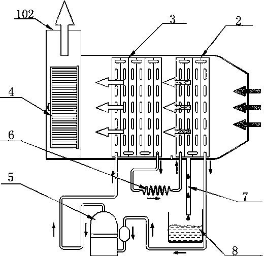
[0051] refer to figure 2 The low condensing pressure deep subcooling high-efficiency dehumidifier includes an air duct 1, a first fan 4 and a refrigeration dehumidification system, and the first fan 4 and the refrigeration dehumidification system are arranged in the air duct 1 side by side. Wherein, the air duct 1 has an air inlet 101 and an air outlet 102, and the first fan 4 is located at the air outlet 102 of the air duct 1; the first fan 4 is preferably a centrifugal fan, and of course other types of fans are also selected, which are not limited here.

[0052] In this embodiment, the refrigeration and dehumidification system includes an evaporator 2, a condenser 3, and a compressor 5, wherein both the evaporator 2 and the condenser 3 include bent pipes and fins arranged outside the bent pipes, wherein the fins can For aluminum fins, bent pipes can be copper pipes. The evaporator 2 and the condenser 3 are arranged side by side, and the evaporator 2 is close to the air inl...

Embodiment 2

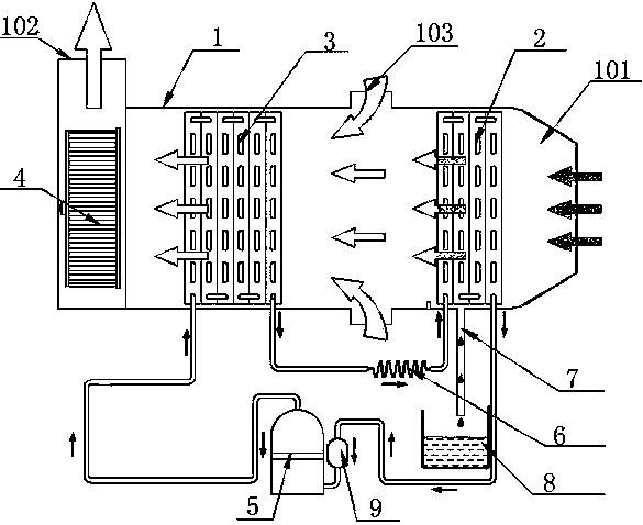
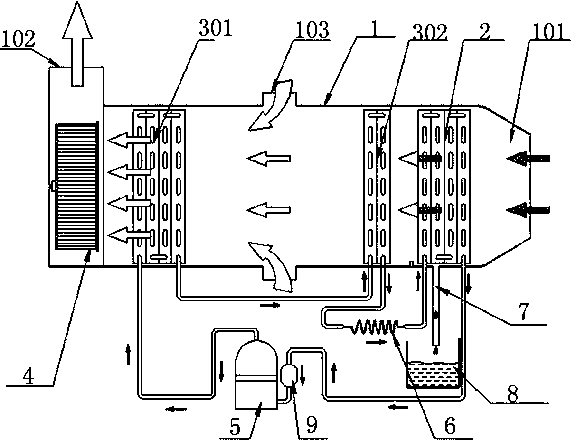
[0063] refer to image 3 , this embodiment is an improvement made on the basis of Embodiment 1. Specifically, in this embodiment, the refrigeration and dehumidification system includes two condensers, specifically a first condenser 301 and a second condenser 302 connected in series, the first condenser 301 and the second condenser 302 are arranged side by side, and the second A condenser 301 is close to the side of the first fan 4, a second condenser 302 is close to the side of the evaporator 2, and the bypass air passage 103 is located between the first condenser 301 and the second condenser 302; the second condenser Both ends of the pipeline in 302 are respectively connected to the pipelines in the first condenser 301 and the evaporator 2 , and the throttling device 6 is arranged on the pipeline between the second condenser 302 and the evaporator 2 .

[0064] In this embodiment, the heat release area of ​​the first condenser 301 is larger than the heat release area of ​​the...

Embodiment 3

[0072] refer to Figure 5 , this embodiment is an improvement made on the basis of the second embodiment. Specifically, a second fan 10 is also provided between the second condenser 302 and the bypass airflow channel 9. For other structures of the low condensing pressure deep subcooling and high-efficiency dehumidifier, refer to the description in Embodiment 2, which will not be repeated here. repeat.

[0073] In this embodiment, the present invention solves the problem of the second condenser 302 and the evaporator 2 compared with the bypass air passage 103 by adding a second fan 10 between the second condenser 302 and the bypass air passage 9 . The large wind resistance in the channel area helps to stabilize the ventilation volume of the second condenser 302 and the evaporator 2, and contributes to the air distribution of the bypass air channel 103, thereby stably increasing the air volume flowing through the condenser 301. Make its air volume reach more than 3 times of th...


PUM


Abstract

The invention provides a low-condensing-pressure deep supercooling efficient dehumidifier. The low-condensing-pressure deep supercooling efficient dehumidifier comprises an air flue, a first draught fan and a refrigerating and dehumidifying system. The refrigerating and dehumidifying system comprises an evaporator, a first condenser, a second condenser, a compressor and a throttling device. According to the low-condensing-pressure deep supercooling efficient dehumidifier, a bypass airflow channel is additionally arranged in the air flue between the first condenser and the second condenser, so that the ventilation quantity of the first condenser is increased, and the condensing pressure of refrigerating fluid gas in the condensers is reduced; the first condenser is used for heat release and cooling of a sensible heat portion of the overheated refrigerating fluid gas and heat release, condensation and liquefaction of the refrigerating fluid gas, and the second condenser is used for cooling and supercooling of refrigerating fluid; since a finned thermal bridge between the first condenser and the second condenser is disconnected, the supercooling degree of the refrigerating fluid at the tail end of the second condenser is improved, the vaporization ratio of the refrigerating fluid in the throttling device can be lowered, the evaporation and heat absorption capacity of the refrigerating fluid in the evaporator is improved, and the energy efficiency ratio of the dehumidifier is increased substantially.

Description

technical field [0001] The invention relates to the technical field of dehumidifier design, in particular to a deep supercooled high-efficiency dehumidifier with low condensation pressure. [0002] Background technique [0003] A dehumidifier is an electrical device that uses refrigeration to reduce the water vapor component in the air and achieve the purpose of reducing the absolute moisture content of the air. Moisture-proof and mildew-proof of crop seeds, electronic products, precision instruments, audio-visual products, paper, clothing, leather goods, medicines, etc., dehumidification in coastal areas and foggy areas, patients suffering from rheumatism and respiratory diseases, as well as the elderly, pregnant women and infants It is especially necessary to create a suitable humidity environment for daily living and nursing care. Therefore, dehumidifiers are widely used in electronic products, precision instruments, food and drug manufacturing workshops, as well as aud...

Claims


Application Information

Patent Timeline
Patent Type & Authority Applications(China)
IPC IPC(8): F25B6/04
Inventor 薛世山李成伟姜城马骥
Owner HANGZHOU PREAIR ELECTRICAL APPLIANCE IND
Why Eureka
Try Eureka