
High-precision long-range surface shape detector for optical surface

A surface and high-precision technology, which is applied in the structural field of optical surface shape detectors, can solve the problems of small optical surface angle range, low reference measurement accuracy, and large lateral displacement of the measurement beam, so as not to be easily disturbed by the external environment, Accurately Measured Effects

Active Publication Date: 2014-09-03
INST OF HIGH ENERGY PHYSICS CHINESE ACADEMY OF SCI
View PDF5 Cites 21 Cited by
  • Summary
  • Abstract
  • Description
  • Claims
  • Application Information

AI Technical Summary

Problems solved by technology

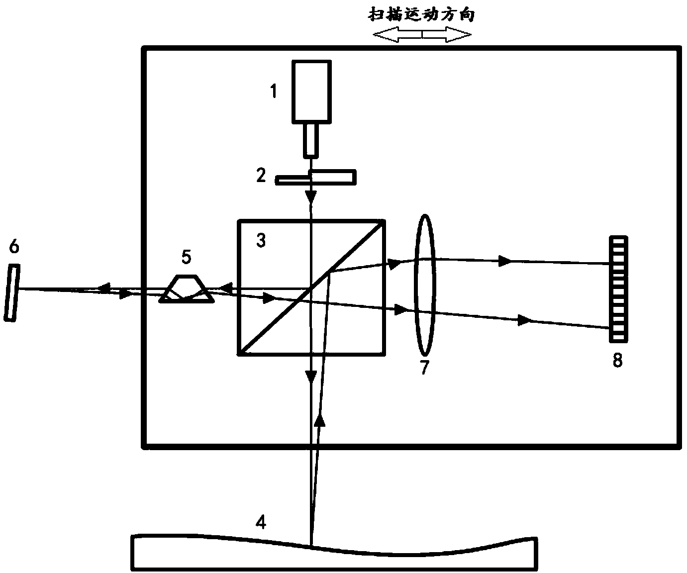
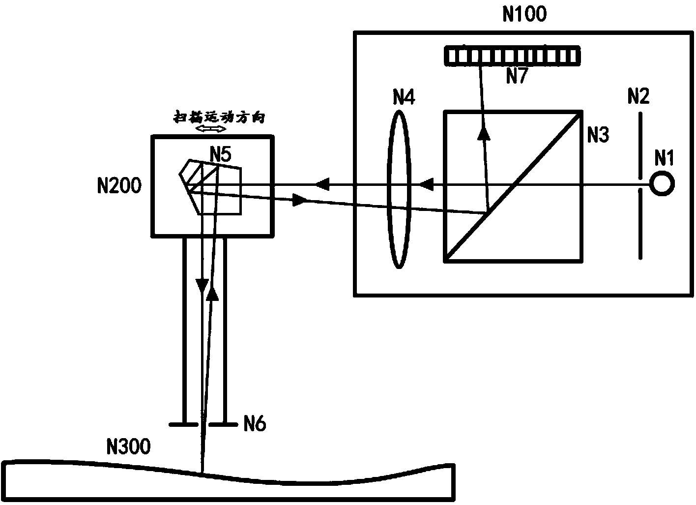
The function of the pentaprism N5 is to maintain a fixed angle between the outgoing beam and the incident beam, and is not affected by the pitch error of the scanning motion of the pentaprism N5 itself, so NOM does not set a reference optical path for scanning motion; the light source of the autocollimator N100 is stably limited , so NOM does not set the light source directivity reference beam
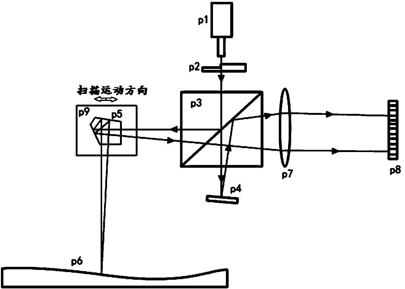
For LTP II, in order to separate the reference beam from the measurement beam on the detector, it is required to tilt the reference beam, resulting in a more serious second lateral displacement
[0020] 2. It is difficult to calibrate the instrument due to the large change in the length of the optical path;
[0021] The above problems can theoretically be alleviated by using standard angle generating equipment for calibration and calibration. However, the calibration data must obtain the calibration data of each incident angle at each lateral position of the optical element of the instrument. Since the lateral position at the same incident angle is determined by the optical path length Therefore, when the optical path length is inclined and changes greatly, it is necessary to calibrate the calibration data of different incident angles (two-dimensional angles in space) under different optical path lengths. This is a three-dimensional calibration, which is difficult to achieve due to the large amount of calibration
In addition, when the measurement application after calibration is completed, the change of optical path length must be provided accurately in real time to utilize the calibration data, which is not easy to achieve
The existing surface shape testing instruments all have the problem of difficult calibration
[0022] 3. The angle range of the optical surface suitable for detection is small;
[0023] For the existing ppLTP and NOM, due to the large optical path length, when measuring the optical surface with a large angle range, the lateral displacement of the measuring beam is large and causes a large error, so it is not suitable for surface shape measurement with a large angle range
[0024] 4. The reference measurement accuracy of scanning motion error and light source pointing error is low
The existing LTP reference measurement introduces optical surface measurement to the same optical head for detection, resulting in the reduction of the reference measurement accuracy of LTP scanning motion error and light source pointing error

Method used


Image

  • High-precision long-range surface shape detector for optical surface
  • High-precision long-range surface shape detector for optical surface
  • High-precision long-range surface shape detector for optical surface

Examples


Embodiment Construction

[0043] Typical embodiments embodying the features and advantages of the present invention will be described in detail in the following description. It should be understood that the present invention can have various changes in different embodiments, all of which do not depart from the scope of the present invention, and the descriptions and drawings therein are essentially for illustrative purposes, rather than limiting this invention.

[0044] Such as Figure 4 As shown, the high-precision long-range optical surface profile detector of the present invention includes a first optical head 100, a reference mirror 300, and a second optical head 200. The first optical head 100 is used to scan the optical element 400 to be tested, the reference mirror 300 is fixedly arranged on the side wall of the first optical head 100, and the second optical head 200 projects a reference beam to the reference mirror 300 and detects the reference mirror 300 For the reflected reference beam 600, th...


PUM


Abstract

The invention discloses a high-precision long-range surface shape detector for an optical surface. The high-precision long-range surface shape detector for the optical surface comprises a first optical head, a reference mirror and a second optical head. The first optical head is used for scanning optical elements to be detected, the reference mirror is fixedly arranged on the side wall of the first optical head, the second optical head projects reference beams to the reference mirror and detects the reference beams reflected by the reference mirror, and the first optical head and the second optical head are different in precision level. According to the high-precision long-range surface shape detector for the optical surface, the first optical head and the second optical head are adopted, the first optical head scans and detects the optical elements to be detected, the second optical head carries out error detection of scanning motion of the first optical head, the precision, the detecting ranges and the beam widths of the two optical heads are set according to different detecting needs and levels, the optical elements to be detected can be detected more accurately, and the high-precision long-range surface shape detector for the optical surface is not prone to being interfered by external environments.

Description

Technical field [0001] The invention relates to an optical surface profile detector, in particular to the structure of a high-precision and long-range optical surface profile detector. Background technique [0002] In scientific research, information technology, aerospace, defense industry, astronomical observation and other fields, especially in the field of synchrotron radiation optical engineering, optical elements with extremely high surface accuracy (1 nanometer, 10 nanoarc) are required. The processing technology of such a high-precision optical element largely relies on high-precision surface shape detection technology. [0003] The commonly used long-range surface shape detectors are based on the f-θ optical system for angle measurement, even if the small beam enters the Fourier transform (FT) lens and uses a linear or area array detector to detect the focal spot pattern on the lens focal plane The position information reflects the angle information of the incident beam. T...

Claims


Application Information

Patent Timeline
IPC IPC(8): G01B11/24
Inventor 李明杨福桂王秋实盛伟繁刘鹏
Owner INST OF HIGH ENERGY PHYSICS CHINESE ACADEMY OF SCI
Learn More