
Direction-of-arrival estimation method based on sparse representation of spatial smoothing covariance matrix

A technology of covariance matrix and direction of arrival angle, applied in the field of signal processing, can solve the problems of unsatisfactory angular resolution, large estimation error, slow response speed of target reconnaissance and passive positioning, etc.

Inactive Publication Date: 2014-09-03
XIDIAN UNIV
View PDF6 Cites 29 Cited by
  • Summary
  • Abstract
  • Description
  • Claims
  • Application Information

AI Technical Summary

Problems solved by technology

In recent years, the L1_SRACV algorithm based on the sparse representation of the array covariance vector, the joint sparse approximation JLZA algorithm, etc. have appeared, but these algorithms have a large amount of calculation, and in the case of low signal-to-noise ratio, the angular resolution is not ideal, and the anti-coherent signal poor performance
However, in practical applications, both target reconnaissance and passive positioning need to be carried out on the basis of angle estimation. The defects in the above algorithms will cause the shortcomings of slow response speed and large estimation errors in target reconnaissance and passive positioning.

Method used


Image

  • Direction-of-arrival estimation method based on sparse representation of spatial smoothing covariance matrix
  • Direction-of-arrival estimation method based on sparse representation of spatial smoothing covariance matrix
  • Direction-of-arrival estimation method based on sparse representation of spatial smoothing covariance matrix

Examples


Embodiment Construction

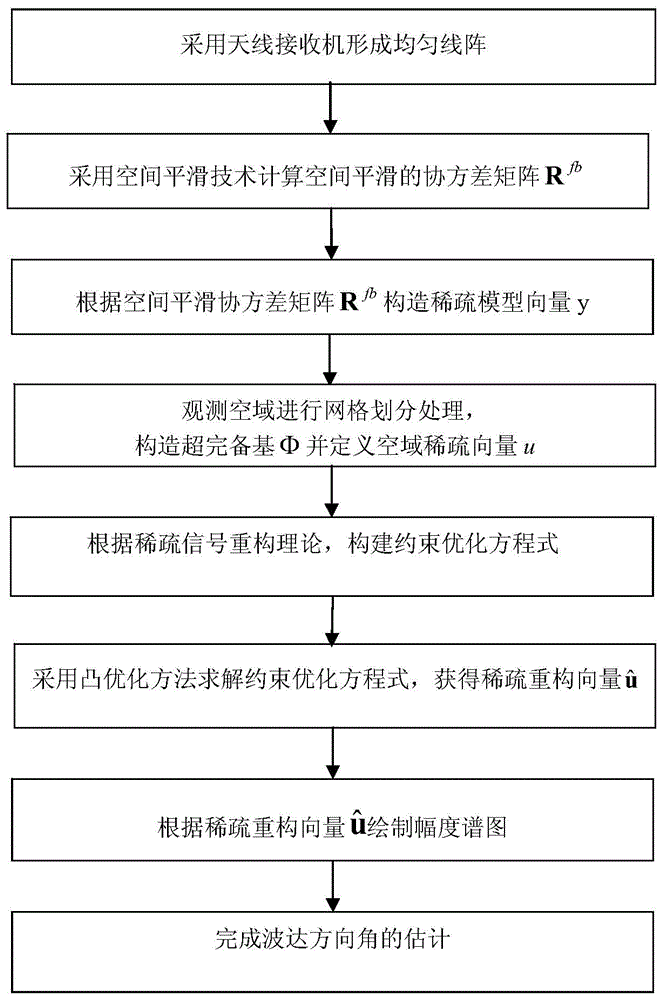
[0043] The technical solutions and effects of the present invention will be further described in detail below with reference to the accompanying drawings.

[0044] refer to figure 1 , the implementation steps of the present invention are as follows:

[0045] Step 1: Use the antenna receiver to form a uniform line array.

[0046] Antenna receivers are placed every interval d, and a total of M are placed to form a uniform linear antenna array. Each antenna receiver is called an array element. Assuming that there are K far-field narrowband signals incident on the uniform linear array, In addition, complex Gaussian white noise with a mean value of zero is added to the signal during propagation, where M≥2, K≥1, 0<d≤λ / 2, and λ is the wavelength of the incident narrowband signal.

[0047] Step 2: Calculate the spatially smoothed covariance matrix R of the antenna array output using the forward-backward spatial smoothing method fb .

[0048] 2a) Using the translation invariance of...


PUM


Abstract

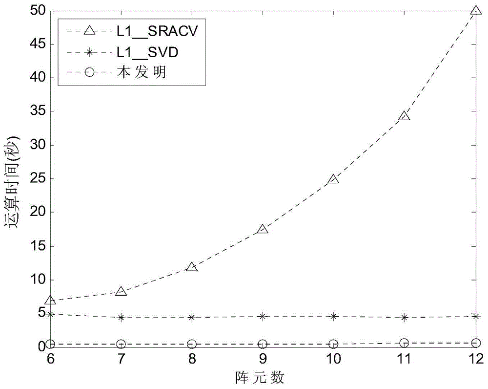
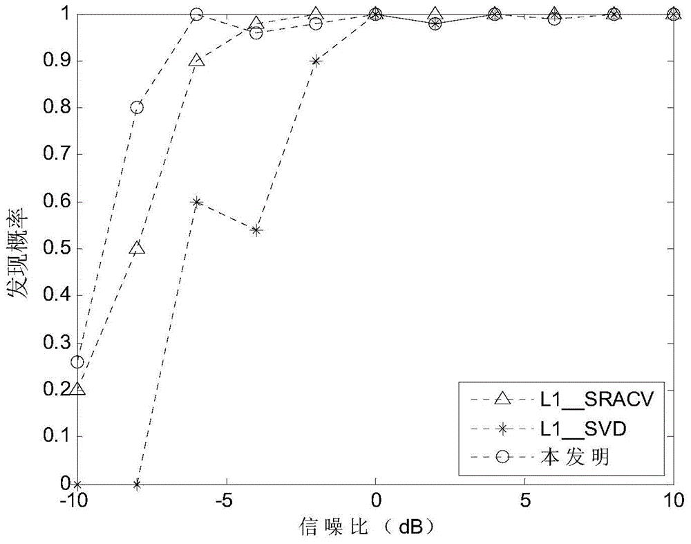
The invention discloses a direction-of-arrival estimation method based on sparse representation of a spatial smoothing covariance matrix. The method mainly solves the problems that the calculation amount is large, the performance of processing coherent signal sources is poor and consequently errors in passive location estimation are large in the prior art. The method comprises the implementation steps: (1) forming a uniform linear array by antenna receivers, (2) the spatial smoothing covariance matrix output by the array is calculated according to the spatial smoothing technology, (3) vectorizing the spatial smoothing covariance matrix to obtain sparse model vectors, (4) carrying out mesh generation on a spatial domain to construct a perfect base, (5) establishing a constrained optimization equation based on the sparse representation relation between the sparse model vectors and the perfect base, (6) solving the constrained optimization equation according to the convex optimization method to obtain an optimal estimation value, and (7) drawing a magnitude spectrum according to the optimal estimation value to obtain the value of direction of arrival. By means of the method, the calculation speed of passive direction finding is increased, and the performance of estimating the coherent signal sources at a low signal-to-noise ratio is improved. The method can be applied to target reconnaissance and passive localization.

Description

technical field [0001] The invention belongs to the technical field of signal processing, in particular to a direction-of-arrival estimation method based on a uniform linear array, which can be used for target reconnaissance and passive positioning. Background technique [0002] Direction of Arrival Angle of Arrival (DOA) estimation is to use antenna arrays at different positions in space to receive signals from multiple signal sources in different directions, and use modern signal processing methods to quickly and accurately estimate the direction of the signal source. It has important application value in other fields. In the research on this problem, subspace-based models such as multiple signal classification (MUSIC) appeared earlier and were widely used, and most subsequent DOA estimation algorithms were generated using this model. In recent years, the compressed sensing theory proposed by Donoho et al. provides a new way of thinking for DOA estimation problems, result...

Claims


Application Information

Patent Timeline
Patent Type & Authority Applications(China)
IPC IPC(8): G01S3/14
CPCG01S3/14
Inventor 蔡晶晶鲍丹刘高高秦国栋武斌李鹏冯小平张银平蔡辉
Owner XIDIAN UNIV
Learn More