
Laser three-dimensional imaging optical transmit-receive system

A laser three-dimensional imaging, transceiver system technology, applied in the field of imaging lidar, can solve the problems of low imaging frame rate, increase the system volume, limit the application of laser imaging technology, etc., and achieve the effect of improving efficiency and speed

Active Publication Date: 2014-09-03
NANJING UNIV
View PDF5 Cites 16 Cited by
  • Summary
  • Abstract
  • Description
  • Claims
  • Application Information

AI Technical Summary

Problems solved by technology

However, the traditional laser imaging technology adopts a point scanning system to obtain images through two-dimensional scanning (line scan + frame scan), resulting in a low imaging frame rate. The highest index reported at present is 20Hz, and the imaging field of view is generally less than 1 °; In addition, due to the application of the scanner, it not only increases the volume of the system, but also reduces the reliability and working stability of the system
These disadvantages limit the application of point-scanning system laser imaging technology

Method used


Image

  • Laser three-dimensional imaging optical transmit-receive system

Examples


Embodiment Construction

[0025] The present invention will be further explained below in conjunction with the accompanying drawings.

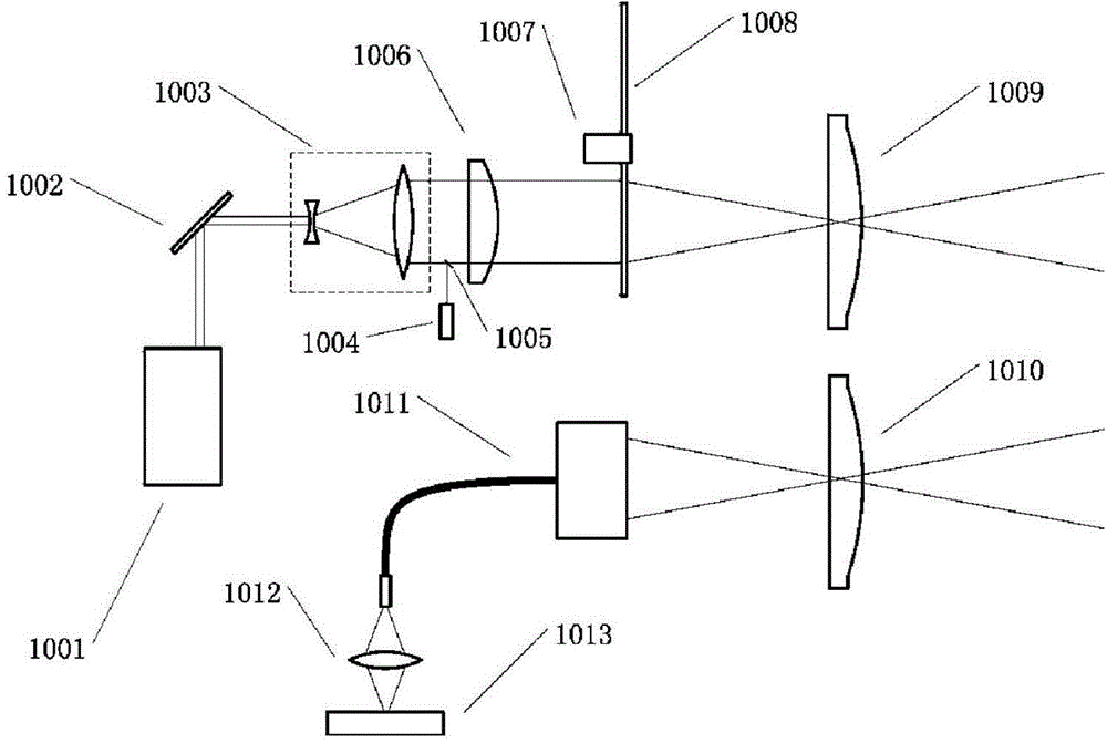
[0026] Such as figure 1 A laser three-dimensional imaging optical transceiver system includes an emission optical part and a detection imaging optical part. Wherein, the transmitting optical part includes a pulsed laser 1001 , a reflecting mirror 1002 , a beam expander 1003 , a photodetector 1004 , a second reflecting mirror 1005 , a cylindrical lens 1006 , a laser coding mechanism 1008 and a transmitting lens 1009 . The pulsed laser 1002 is used to generate laser pulses. Here, a semiconductor-pumped solid-state laser is used. The laser has small volume and power consumption and is easy to maintain. The wavelength of the laser pulse emitted by the pulsed laser 1002 is 532nm, the pulse width is 1-20ns, and the working frequency is 3-20KHz. The beam expander 1003 , the cylindrical lens 1006 and the emitting lens 1009 are arranged coaxially, and the laser coding mechani...


PUM


Abstract

The invention discloses a laser three-dimensional imaging optical transmit-receive system. According to the system, a round laser beam is shaped into a narrow strip shape, a coding disc rotating at a high speed is adopted to divide the strip-shaped laser beam into multiple sections of codes, a projection lens transmits the coded laser beam, target reflected light of corresponding image points in the multiple sections is combined by a receiving end by means of a fiber optic image transmission beam and is received by an area array photoelectric sensor, and then altitude data of multiple image points can be measured by each sensor detection unit. According to the system, the method is novel, and high-efficiency and high-seed three-dimensional measurement under the condition of a large visual field can be achieved.

Description

technical field [0001] The invention belongs to the technical field of laser three-dimensional imaging, and in particular relates to an imaging laser radar for realizing push-broom three-dimensional measurement based on laser code multiplexing technology. Background technique [0002] 3D imaging lidar technology is suitable for high-speed imaging of large-scale areas such as 3D construction of digital cities, natural disaster rescue, and digital earth. The 3D imaging lidar technology adopts the method of actively emitting laser light to illuminate the target, uses the photoelectric detector to receive the echo signal reflected by the target, extracts the 3D information of the target including elevation information, and reconstructs the 3D graphics of the target. It is currently the only technology that can directly acquire the 3D image of the target at the same time, and has high military and civilian application value. However, the traditional laser imaging technology adop...

Claims


Application Information

Patent Timeline
Patent Type & Authority Applications(China)
IPC IPC(8): G01S17/89G01S7/481G01S7/483
CPCG01S7/4811G01S7/483G01S7/4865G01S17/89
Inventor 韩小纯王元庆张冰清
Owner NANJING UNIV
Learn More