Switch converter and control circuit and method thereof

A switching converter, control circuit technology, applied in control/regulation systems, DC power input conversion to DC power output, instruments, etc., can solve the problem that the compensation signal RAMP is small, the compensation signal RAMP is difficult to adapt to wide input applications, and the compensation signal Large RAMP and other problems, to avoid jitter and sub-harmonic oscillation, improve dynamic response and load regulation

Active Publication Date: 2014-09-03
CHENGDU MONOLITHIC POWER SYST
View PDF3 Cites 56 Cited by
  • Summary
  • Abstract
  • Description
  • Claims
  • Application Information

AI Technical Summary

Problems solved by technology

this means, figure 1 The compensation signal RAMP shown is difficult to adapt to wide input applications
In case of...

Method used


Image

  • Switch converter and control circuit and method thereof
  • Switch converter and control circuit and method thereof
  • Switch converter and control circuit and method thereof

Examples


Embodiment Construction

[0029] Specific embodiments of the present invention will be described in detail below, and it should be noted that the embodiments described here are only for illustration, not for limiting the present invention. In the following description, numerous specific details are set forth in order to provide a thorough understanding of the present invention. It will be apparent, however, to one of ordinary skill in the art that these specific details need not be employed to practice the present invention. In other instances, well-known circuits, materials or methods have not been described in detail in order to avoid obscuring the present invention.

[0030] Throughout this specification, reference to "one embodiment," "an embodiment," "an example," or "example" means that a particular feature, structure, or characteristic described in connection with the embodiment or example is included in the present invention. In at least one embodiment. Thus, appearances of the phrases "in on...


PUM


Abstract

The invention discloses a switch converter with constant connection time control, and a control circuit and method thereof. A compensation control signal is generated according to the input voltage or a control signal, and a compensation signal is adjusted according to the compensation control signal so that the compensation signal can be adjusted to a proper value within a wide input range. Compared with the prior art, jittering and subharmonic oscillation under low input can be avoided, and dynamic response and load adjusting rate under high input are improved.

Description

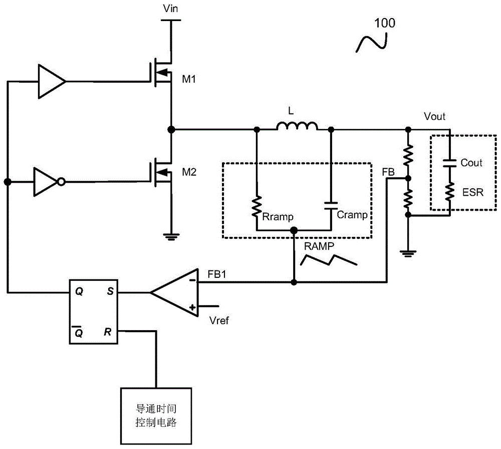
technical field [0001] Embodiments of the present invention relate to electronic circuits, and in particular to switching converters and their control circuits and control methods. Background technique [0002] Constant on-time control has been well applied in the field of power supplies due to its superior load transient response, simple internal structure and smooth operation mode switching. However, for switching converters using constant on-time control, even if ceramic capacitors are used as output capacitors, the output voltage may still produce sub-harmonic oscillations due to insufficient equivalent series impedance of the output capacitors. [0003] In order to prevent sub-harmonic oscillation, a common practice is to introduce a compensation signal that is in phase with the inductor current. figure 1 It is a schematic circuit diagram of a traditional switching converter 100 controlled by constant on-time control, wherein a slope compensation generating circuit com...

Claims


Application Information

Patent Timeline
IPC IPC(8): H02M3/157
CPCH02M3/156H02M1/0022H02M1/0025
Inventor 袁伟欧阳茜
Owner CHENGDU MONOLITHIC POWER SYST
Why Eureka
Try Eureka