Switch reluctance motor rotor-less position sensor control method

A technology of switched reluctance and rotor position, applied in the direction of single motor speed/torque control, AC motor control, electronic commutator, etc. Operation and other issues, to achieve the effect of strong practicability and versatility, good dynamic response performance and stability, and strong real-time performance

Active Publication Date: 2014-09-03
CHINA UNIV OF MINING & TECH
View PDF4 Cites 6 Cited by
  • Summary
  • Abstract
  • Description
  • Claims
  • Application Information

AI Technical Summary

Problems solved by technology

However, the rotor position sensor commonly used in the current switched reluctance motor system is prone to failure due to harsh environments such as dust, oil, collisions, etc., so that the control system cannot obtain the correct position signal, resulting in wrong phase commutation or disordered operation of the system, which is extremely serious. Greatly affects the reliability of the entire system
The control method without rotor position sensor has always been a research hotspot, but it has not been popularized and applied so far. Among them, the high-frequency signal injection method of the non-conducting phase is only suitable for lower speed ranges, and the flux linkage real-time observation method requires integral calculation. In the chopper control mode, the phase winding terminal voltage repeats several times in a current cycle, which requires high A / D detection accuracy and frequency, and the change of the motor phase winding resistance also significantly affects the accurate calculation of the flux linkage, and it is difficult to obtain satisfactory results.

Method used


Image

  • Switch reluctance motor rotor-less position sensor control method
  • Switch reluctance motor rotor-less position sensor control method
  • Switch reluctance motor rotor-less position sensor control method

Examples


Embodiment 1

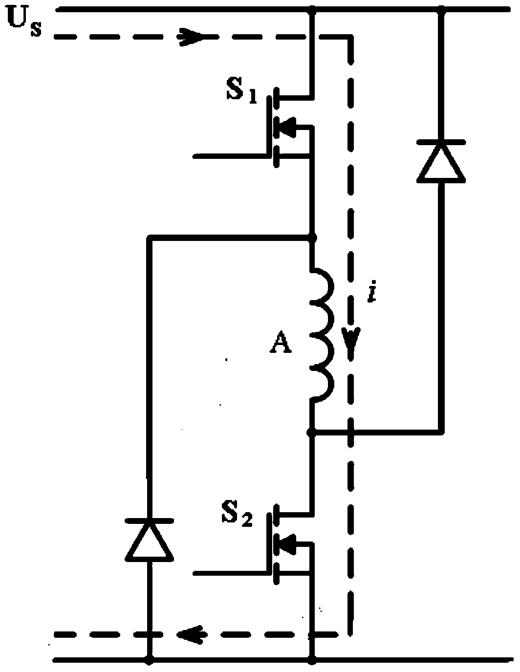
[0010] Embodiment one, as figure 1 As shown, taking the switched reluctance motor system with two-switch power converter per phase as an example,

[0011] The main switch S of phase A in the power converter 1 and S 2 Turn on, the phase winding of the switched reluctance motor receives a positive voltage U S Excitation, A-phase current i path in the power converter;

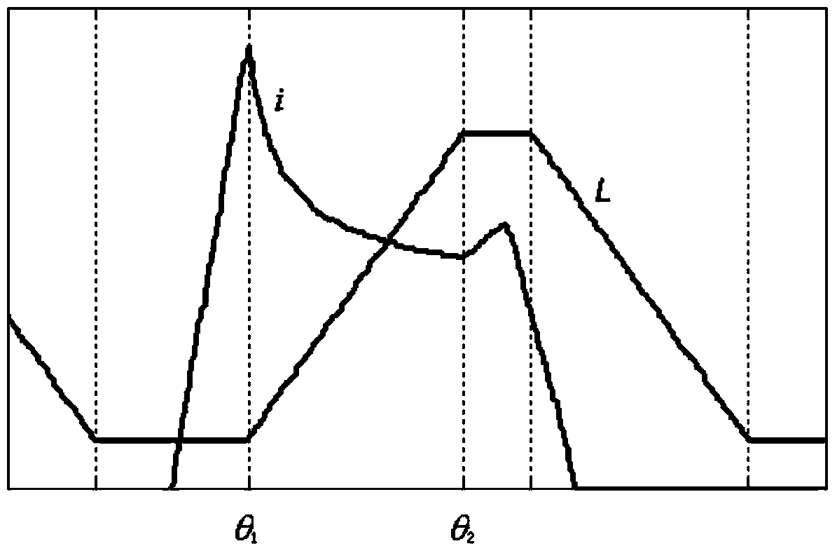
[0012] figure 2 As shown, the phase winding current i is detected, and the phase A winding current i rises first until the phase winding current i reaches the highest peak value θ 1 position, then the phase winding current i starts to drop, and drops to the valley value θ 2 position, the phase winding current i continues to rise; when the phase A current drops to the valley value θ 2 position, the phase winding current valley value θ 2 The position is the starting rotor position of the maximum phase inductance L of phase A, and the phase winding current valley value θ of the starting rotor position of the ...

Embodiment 2

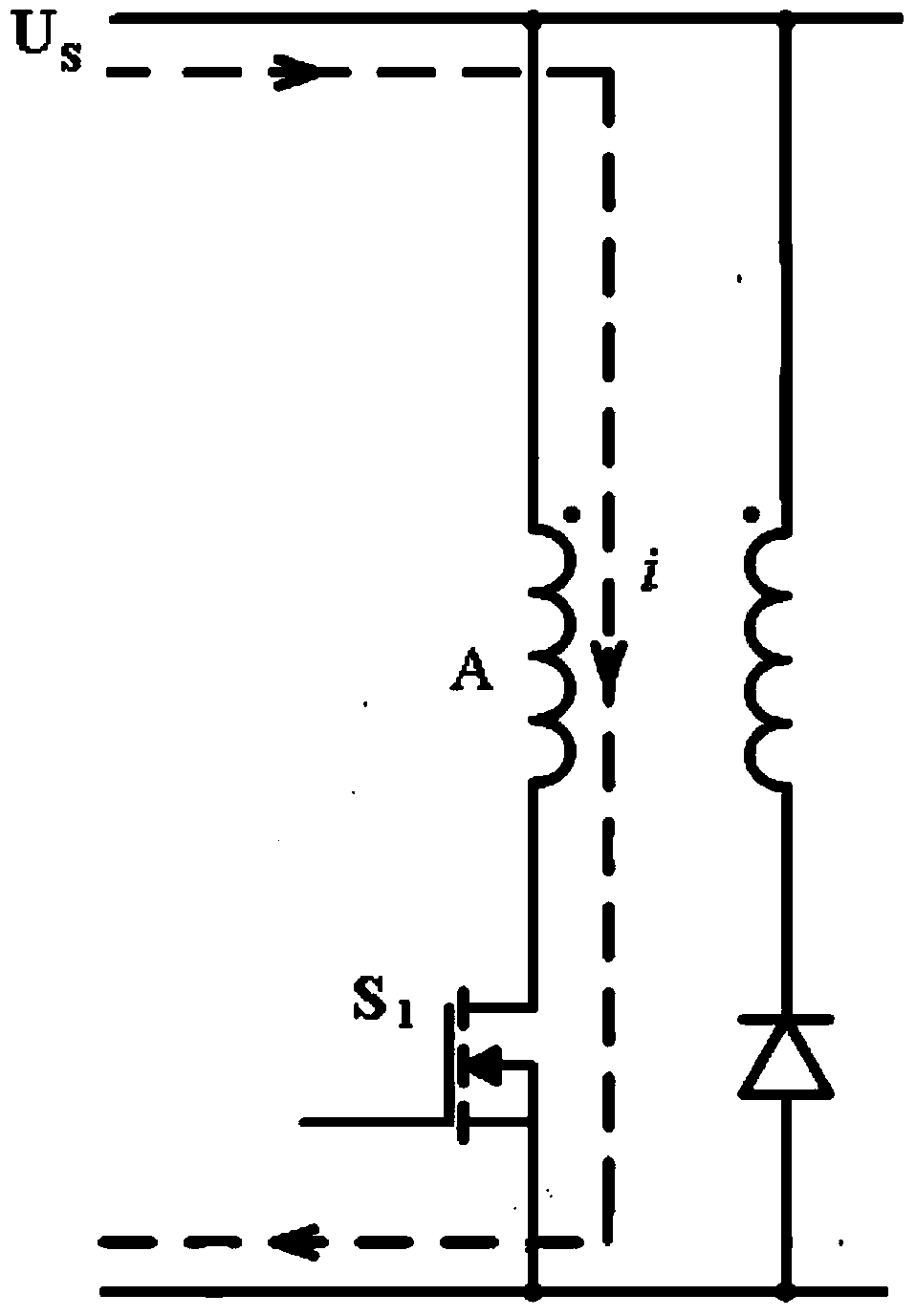
[0013] Embodiment two, such as image 3 As shown, taking a switched reluctance motor system with a two-winding power converter per phase as an example,

[0014] The main switch S of phase A in the power converter 1 Turn on, the phase winding of the switched reluctance motor receives a positive voltage U S Excitation, phase current i path;

[0015] Such as figure 2 As shown, the phase winding current i is detected, and the phase A winding current i rises first until the phase winding current i reaches the highest peak value θ 1 position, then the phase winding current i drops to the valley value of the phase winding current θ 2 position, the phase winding current i continues to rise; when the phase A current drops to the valley value θ 2 position, the phase winding current valley value θ 2 The position is the rotor position at the beginning end of the maximum phase inductance L of phase A, and the phase winding current valley value θ at the beginning end rotor position o...


PUM


Abstract

The utility model discloses a switch reluctance motor rotor-less position sensor control method. According to the method, one main switch in a power converter is opened, a phase winding of the switch reluctance motor is excited by positive voltage, a current of the phase winding increases firstly till the current of the phase winding reaches to a peak value, then the current of the phase winding decreases to a valley value position, the current of the phase winding continuously increases again, the valley value position of the current of the phase winding is a largest-phase-inductance initial end rotor position, the largest-phase-inductance initial end rotor position is acquired and is directly taken as a switch-off position of the main switch of the switch reluctance motor power converter, and the main switch of the power converter is switched off. The method does not need to have a rotor position sensor and does not need to store motor linkage data, and the method further has advantages of strong timeliness, dynamic response performance, good stability and relatively strong practicality and versatility.

Description

technical field [0001] The invention relates to a control method for a switched reluctance motor without a rotor position sensor, which is suitable for switched reluctance motor systems with various power converter topologies and various phase numbers. Background technique [0002] The switched reluctance motor system must work in a self-synchronous state. The position closed loop is the basic condition for the normal operation of the system. Through the feedback signal of the rotor position sensor, the control system can ensure that the motor phase windings are conducted in accordance with the predetermined target sequence and commutate at the correct position. At the same time, the position information is also used as the speed feedback signal of the switched reluctance motor to realize the closed-loop control of the speed of the switched reluctance motor system. Therefore, the rotor position sensor in the switched reluctance motor system is very important, and the rotor p...

Claims


Application Information

Patent Timeline
Patent Type & Authority Applications(China)
IPC IPC(8): H02P6/08
CPCH02P6/18H02P25/08
Inventor 陈昊曾辉
Owner CHINA UNIV OF MINING & TECH
Why Eureka
Try Eureka