
Variable hydraulic damping torsion vibration reduction device

A torsional vibration damping and hydraulic damping technology, applied in the directions of rotational vibration suppression, spring/shock absorber, vibration suppression adjustment, etc., can solve the problems of poor versatility, economic loss, etc. The effect of suppressing the effect

Inactive Publication Date: 2014-09-10
HANGZHOU DIANZI UNIV
View PDF4 Cites 19 Cited by
  • Summary
  • Abstract
  • Description
  • Claims
  • Application Information

AI Technical Summary

Problems solved by technology

[0003] At present, in order to avoid resonance, alleviate the impact load on the transmission system, and improve the life of parts, the torsional vibration of the transmission system is usually suppressed by spring-type torsional dampers or mass flywheel-type torsional dampers. These torsional vibration dampers Both devices can effectively suppress torsional vibration, but they all have their own shortcomings, and the degree of suppression cannot be changed according to the actual vibration situation, so the versatility is poor, and each transmission system needs to manufacture a matching torsional vibration damper In order to achieve a good suppression effect and cause economic losses

Method used


Image

  • Variable hydraulic damping torsion vibration reduction device
  • Variable hydraulic damping torsion vibration reduction device
  • Variable hydraulic damping torsion vibration reduction device

Examples


Embodiment Construction

[0019] The present invention will be further described below in conjunction with accompanying drawing.

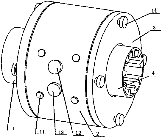
[0020] Such as figure 1 As shown, the variable hydraulic damping torsional vibration damping device of the present invention includes a flange 1, a torsional vibration damping component and an end cover 3. The flange 1 and the end cover 3 are respectively located on both sides of the annular shell 2 and are fixed by fixing screws. 14 is connected with it to form an integral rotating part.

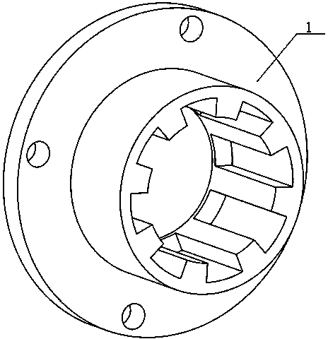
[0021] Such as figure 2 As shown, the flange 1 is connected to the annular housing 2 on the one hand, and connected to the driven rotating shaft through a spline on the other hand, so as to transmit the torque from the torsional vibration damping component to the driven rotating shaft.

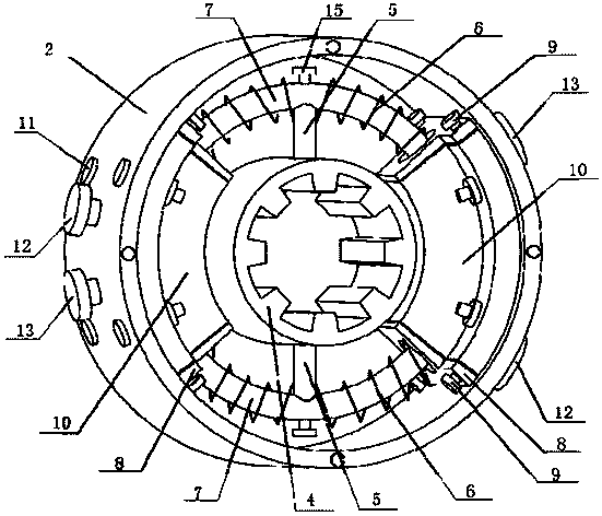
[0022] Such as image 3 As shown, the torsional damping component is composed of an annular housing 2, a hydraulic cylinder 10, a sealing ring 16, a piston push rod 7, a hydraulic cylinder cover 8, a...


PUM


Abstract

The invention discloses a variable hydraulic damping torsion vibration reduction device which comprises a flange plate, a torsion vibration reduction assembly and an end cover. The flange plate and the end cover are arranged on the two sides of an annular shell respectively and are connected with the annular shell through screws to form an overall rotary component. The torsion vibration reduction assembly comprises a shaft coupling barrel, connecting rods, piston push rods, hydraulic cylinders and adjusting screws. The shaft coupling barrel is connected with a driving rotary shaft, the driving rotary shaft drives the shaft coupling barrel to rotate, the piston push rods are driven to rotate through the connecting rods, the piston push rods compress vibration reduction springs, and extrude hydraulic oil, the hydraulic oil is made to pass through oil channels in the piston push rods and flow to the other hydraulic cylinder, the adjusting screws capable of adjusting the flow of the hydraulic oil are arranged on the piston push rods, and therefore the function of variable hydraulic damping torsion vibration reduction is achieved. The variable hydraulic damping torsion vibration reduction device is simple in structure, convenient to dismount, mount and maintain, capable of achieving the function of variable hydraulic damping torsion vibration reduction and good in torsion vibration reduction effect.

Description

technical field [0001] The invention relates to a torsional vibration damping device, in particular to a variable hydraulic damping torsional vibration damping device connecting two transmission shafts. Background technique [0002] The torsional vibration of the transmission system widely exists in the process of industrial production and automobile driving, such as the torsional vibration of the main transmission system caused by acceleration and deceleration, gear meshing, etc. The torsional vibration and the vertical vibration of the rolling mill are coupled with each other, thereby affecting the quality of the plate and strip products. To improve the quality of the plate and strip, the torsional vibration of the main drive system must be suppressed; the torsional vibration of the drive system will generate noise during the driving process of the car, which will affect the ride. Comfort, torsional vibration will affect the life of the transmission shaft and other compone...

Claims


Application Information

Patent Timeline
IPC IPC(8): F16F15/16F16F15/134
Inventor 王桥医王乾坤张泽方敏陈娟
Owner HANGZHOU DIANZI UNIV
Learn More