Deep sea high power led fish lamp
What is Al technical title?
Al technical title is built by PatSnap Al team. It summarizes the technical point description of the patent document.
A high-power, fish-collecting lamp technology, applied in fishing, lighting applications, applications, etc., can solve the problem of inability to solve the problem of seawater corrosion of fish-collecting lamps and taking into account heat dissipation, small underwater irradiation distance of fish-collecting lamps, and low single-module power. and other problems, to achieve the effect of good thermal conductivity, energy saving and efficiency improvement
Active Publication Date: 2017-01-25
JIMEI UNIV
View PDF7 Cites 0 Cited by
Summary
Abstract
Description
Claims
Application Information
AI Technical Summary
This helps you quickly interpret patents by identifying the three key elements:
Problems solved by technology
Method used
Benefits of technology
Problems solved by technology
There are problems in this invention: 1. The fish-collecting lamp adopts corrosion-resistant aluminum alloy and surface plastic powder, which cannot solve the contradiction of seawater corrosion and heat dissipation of the fish-collecting lamp; 2. The LED module uses four blue and green lamp beads with a spacing of 30mm arranged alternately. It will inevitably lead to small power, large size, small luminous flux and small underwater irradiation distance of the fish-collecting lamp.
Method used
Image
Click on the blue label to locate the original text in one second.
Reading with bidirectional positioning of images and text.
Examples
Embodiment Construction
[0028] The present invention will be further described below in conjunction with drawings and embodiments.
[0029] Take the 900W equilateral hexagonal prism structure deep-sea high-power LED fish-collecting lamp as an example.
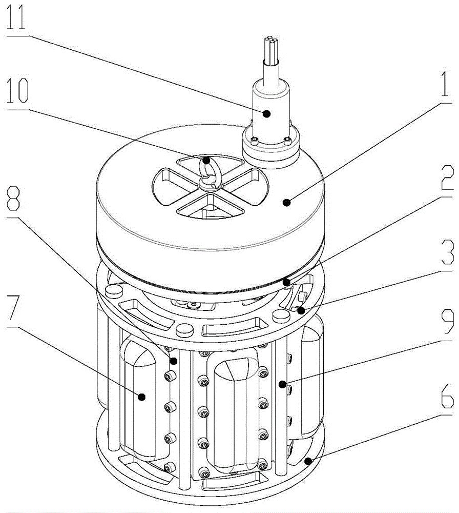
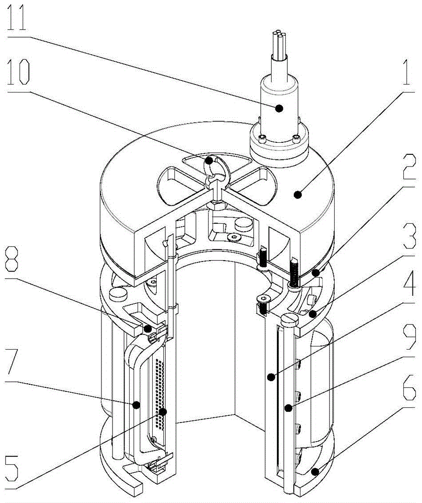
[0030] Such as figure 1 and 2 As shown, the embodiment of the present invention is provided with a high-power COB light-emitting module, a water cooling channel and an underwater connector 11; the high-power COB light-emitting module is provided with a lamp holder 4, a COB light source 5, a Fresnel lens 7, a lens Pressing plate 8, the water-cooling channel is provided with a cover plate 1, an orifice plate 2, an upper plate 3, and a lower plate 6.
[0031] The lamp holder 4 is a hollow hexagonal prism, and each surface of the hexagonal prism is respectively fixed with a COB light source 5, a Fresnel lens 7, and a lens pressure plate 8 from the inside to the outside, and is fastened by screws. The guide hole is connected to the power line, and the p...
PUM
Abstract
The invention relates to underwater fish gathering lamps, in particular to a deep-sea high-power LED fish gathering lamp which comprises a high-power COB (chip on board) light emitting module, a water cooling passage and an underwater connector. The light emitting module comprises a lamp seat, COB light sources, Fresnel lenses and lens pressing plates, the water cooling passage comprises a cover plate, a hole plate, an upper plate and a lower plate, the lamp seat is a hollow polygon prism, the corresponding COB light source, the corresponding Fresnel lens and the corresponding lens pressing plate are fixed on each face of the polygon prism form inside to outside respectively, each COB light source is connected with a power source line through a guide hole in the lamp seat, a submarine cable is connected with the cover plate through the underwater connector to realize underwater sealing, the upper plate is arranged at the top of the lamp seat, the middle portion of the upper plate is hollow while the edge of the same is hollowed, the hole plate is arranged on the upper portion of the upper plate, the middle portion of the hole plate is hollow while the side face of the same is hollowed, the cover plate is arranged on the upper portion of the hole plate, sealing glue is coated on a matching face of the cover plate, the hole plate, the upper plate and the lamp seat, a lower concave cavity of the cover plate and the hole plate form a sealed cavity, the lower plate is arranged at the bottom of the lamp seat, the lower plate and the upper plate are fastened through screws, and the underwater connector is hermetically fixed on the cover plate.
Description
technical field [0001] The invention relates to an underwater fish-collecting lamp, in particular to a deep-sea high-power LED fish-collecting lamp. Background technique [0002] Traditional underwater fish-collecting lamps for light-lure fishing at sea mostly use metal halide bulbs as the light source, and the fuel consumption of fish-collecting lamps accounts for more than 30% of the total fuel consumption of the fishery. It has become a bottleneck restricting the development of pelagic fisheries. Because the metal halide lamp is a full-spectrum light source, when working under the ocean, about 90% of the luminous flux is absorbed by the seawater, and only about 10% of the blue-green light can be transmitted in the seawater, resulting in a great waste of energy. [0003] Chinese patent CN101329040 discloses a high-power blue-green light LED marine underwater fish-collecting lamp. In the lamp body, the upper end of the main housing is fixed to the upper housing, the upper ...
Claims
Application Information
Patent Timeline
Application Date:The date an application was filed.
Publication Date:The date a patent or application was officially published.
First Publication Date:The earliest publication date of a patent with the same application number.
Issue Date:Publication date of the patent grant document.
PCT Entry Date:The Entry date of PCT National Phase.
Estimated Expiry Date:The statutory expiry date of a patent right according to the Patent Law, and it is the longest term of protection that the patent right can achieve without the termination of the patent right due to other reasons(Term extension factor has been taken into account ).
Invalid Date:Actual expiry date is based on effective date or publication date of legal transaction data of invalid patent.