Annular flame type bio-oil burner

A technology of biomass oil and burners, which is applied in the direction of burners, lighting and heating equipment, etc., and can solve the problems of single fire jet, high smoke value of combustion, and loud noise

Active Publication Date: 2014-09-10
XIAMEN XINYESHENG ENERGY TECH
View PDF9 Cites 0 Cited by
  • Summary
  • Abstract
  • Description
  • Claims
  • Application Information

AI Technical Summary

Problems solved by technology

[0003] In the existing burners, fuel oil such as petroleum or diesel oil enters the oil guide pipe through the oil pump, is transported to the oil nozzle, and is ignited by the igniter, and there is only one flame outlet. Biomass oil is a complex mixture of water and impurities. Using existing burners, it is impossible to achieve stable and complete combustion of biomass oil, and the combustion smoke value is high and the noise is loud.
[0004] Chinese document CN 201954541 U provides a kind of biomass oil burner, and it has oil inlet pipe, air inlet pipe and mixing pipe to be connected, and mixing pipe has multiple outlet holes to spray out multiple strands of biomass oil, and in deflector plate Under the action of the atomized biomass oil, the atomized biomass oil is further in full contact with the air; Chinese document CN 201866763 U discloses a biomass oil burner, the lower end of the burner is provided with a secondary air inlet and the length of the burner combustion chamber is relatively short so that the oil The nozzle is on the top of the burner, and other structures are basically the same as CN 201954541 U. There is only one burner port for biomass oil in the two documents, and the flame jet flow is single, resulting in insufficient combustion

Method used


Image

  • Annular flame type bio-oil burner
  • Annular flame type bio-oil burner

Examples


Embodiment

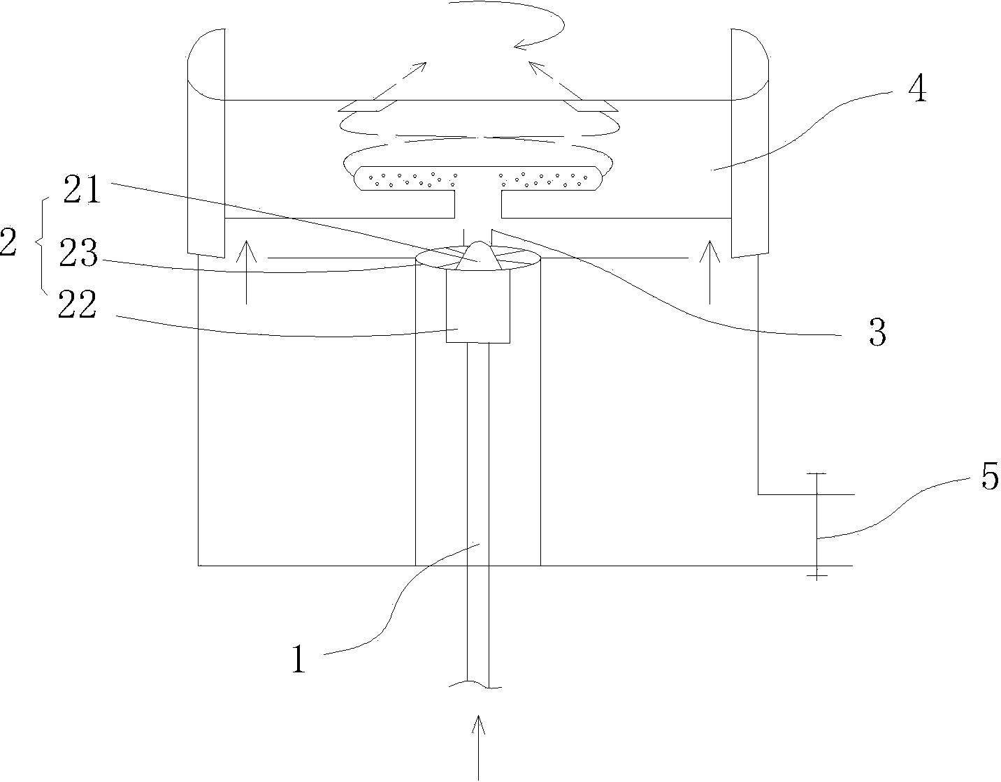
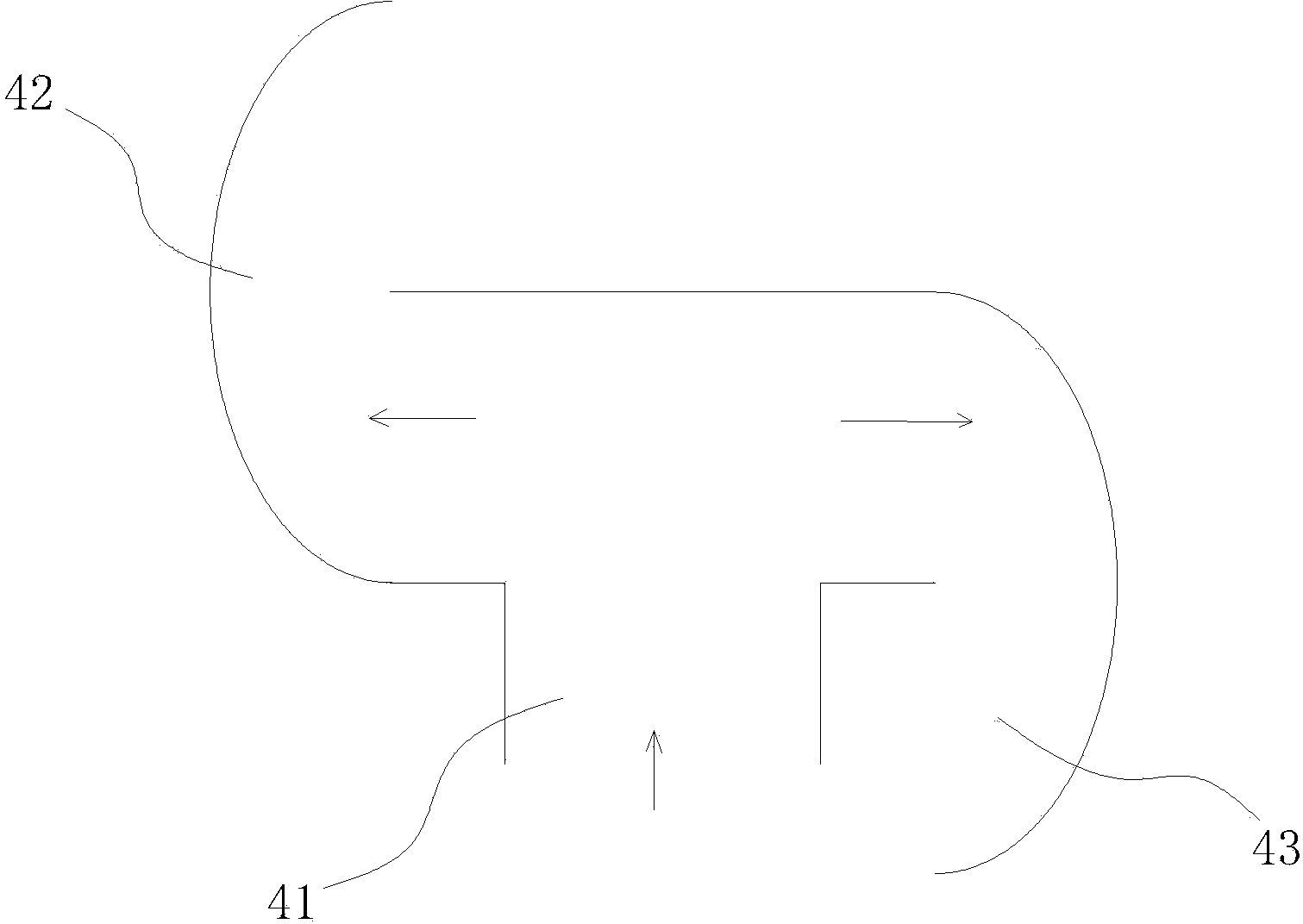
[0020] Example: see figure 1 , a circulating flame type biomass oil burner, the burner is provided with an oil guide pipe 1, the bottom end of the oil guide pipe 1 is the inlet of biomass oil, the other end of the oil guide pipe is connected to the combustion head 2, and an igniter 3 is provided on one side of the combustion head , a combustion hood 4 is provided on the combustion head 2, and N flame flow channels are arranged in the combustion hood 4, wherein N≥2, and the bottom end of each flow channel is connected to a flame inlet 41, and the flame inlet matches the flame nozzle of the combustion head Each flame channel is a spiral ascending channel, and the flames sprayed from the outlets of each channel are sprayed to the central axis of the combustion hood and crossed and split to form a ring structure. The cylinder wall side of this burner is provided with air inlet 5. Combustion head 2 comprises oil nozzle 21 and oil nozzle seat 22 and steady flame dish 23, and steady...


PUM


Abstract

The invention discloses an annular flame type bio-oil burner. An oil guide tube is arranged in a burner body, the bottom end of the oil guide tube is provided with a bio-oil inlet, the other end of the oil guide tube is provided with a combustion head, one side of the combustion head is provided with an igniter, a combustion cover is arranged above the combustion head, N flame passages are arranged in the combustion cover, N > / = 2, the bottom ends of the passages are connected to a flame inlet matching with the flame spraying port of the combustion head, the flame passages are in upward spiral types, and the flame sprayed from the flame passages are in an annular structure. The direction of the air flow outside the flame spraying port is divided into two or multiple directions under the effect of resistance, the annular flame is formed outside the spraying port, the combustion time of a hearth is increased, the combustion is performed completely, a smoke value is low, the combustion space is increased by the arrangement of the flame passages, vibration force is reduced, and noise is small.

Description

technical field [0001] The invention discloses a circulating flame type biomass oil burner, which belongs to the technical field of combustion appliance manufacturing according to the International Patent Classification (IPC), and in particular relates to a combustion application device of biomass oil. Background technique [0002] Biomass oil, as the only renewable energy that can be directly converted into liquid fuels, converts renewable biomass resources into clean high-grade liquid fuels to partially replace petroleum, heavy oil, diesel and coal tar, etc., not only can get rid of the limited Over-reliance on petroleum resources can greatly reduce the emission of pollutants and greenhouse gases, improve the environment and protect the ecology. [0003] In the existing burners, fuel oil such as petroleum or diesel oil enters the oil guide pipe through the oil pump, is transported to the oil nozzle, and is ignited by the igniter, and there is only one flame outlet. Biomas...

Claims


Application Information

Patent Timeline
Patent Type & Authority Applications(China)
IPC IPC(8): F23D11/36F23D11/38
Inventor 钟庆有李志贵周思安
Owner XIAMEN XINYESHENG ENERGY TECH
Why Eureka
Try Eureka