Two-slit interference fringe decoding spectrum confocal displacement sensor and displacement measurement method thereof

A displacement sensor, double-slit interference technology, applied in measurement devices, instruments, optical devices, etc., can solve the problems affecting the linearity of the sensor, the drift of detection wavelength, the difficulty of system installation and adjustment, etc., to improve the measurement accuracy and stability, The effect of improving the sensitivity of displacement measurement and improving the signal-to-noise ratio

Inactive Publication Date: 2014-09-10
XIAN TECHNOLOGICAL UNIV
View PDF8 Cites 30 Cited by
  • Summary
  • Abstract
  • Description
  • Claims
  • Application Information

AI Technical Summary

Problems solved by technology

At present, the typical grating spectrometer generally adopts the Czerny-Turner system or the flat-field holographic concave grating system. The former needs to undergo multiple refraction and reflection, and the structure is complex, which greatly increases the difficulty of system installation and adjustment, while the flat-field holographic concave grating is difficult to design and manufacture. high
On the whole, the light-splitting method of the grating spectroscopy ceremony is complicated in principle and high in cost
In addition, the detection wavelength of the spectrometer will drift with time and the environment, requiring regular calibration, which affects the measurement accuracy of the sensor
Moreover, the nonlinearity of the spectrometer itself directly affects the linearity of the sensor

Method used


Image

  • Two-slit interference fringe decoding spectrum confocal displacement sensor and displacement measurement method thereof
  • Two-slit interference fringe decoding spectrum confocal displacement sensor and displacement measurement method thereof
  • Two-slit interference fringe decoding spectrum confocal displacement sensor and displacement measurement method thereof

Examples


Embodiment Construction

[0045] The present invention will be described in detail below in combination with specific embodiments.

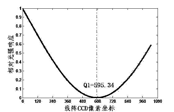
[0046] The invention relates to a double-slit interference fringe decoding spectral confocal displacement sensor, which is a sensor that uses double-slit interference + 1st-level dark fringe judgment to realize the wavelength-displacement decoding of the spectral confocal displacement sensor, and the +1st-level dark fringe center The position changes linearly with the displacement of the measured object.

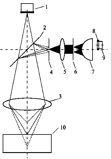
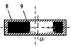
[0047] see figure 1 , the sensor is sequentially provided with a broadband point light source 1, an achromatic beam splitter 2 and a dispersive lens group 3 from top to bottom. Double slit screen 6, adapter lens 7, rectangular diaphragm 8 and linear array CCD9. The broadband point light source 1 works in the visible light range, and the specific wavelength range is 400nm-760nm. The confocal pinhole 4 , the achromatic collimator lens 5 , the interference double-slit s...


PUM


Abstract

The invention relates to a two-slit interference fringe decoding spectrum confocal displacement sensor and a displacement measurement method thereof. A grating spectrometer is used in a spectrum analyzing unit of a current spectrum confocal displacement sensor, the beam split principle is complex, cost is high, detected wavelength can drift along with time and environment, and the measuring accuracy of the sensor is affected. The sensor comprises a broadband point light source, a non-aberration spectroscope, a dispersing lens group, a confocal pinhole, a non-aberration collimating lens, an interference two-slit screen, an adaptive lens, a rectangular diaphragm and a linear array CCD. Reflected light of the surface of a measured object is subjected to filtering through the confocal pinhole, then quasi-monochromatic light is formed, after non-aberration collimating, the quasi-monochromatic light is divided into two sub column face light sources by two slits, interference is formed, the widths of the interference fringes and the wavelength of the reflected light of the surface of the measured object are in good linear relation, and by interpreting the widths of the interference fringes, measuring of object displacement is achieved. The displacement sensor and the method have the advantages of being low in cost, good in linearity and high in resolution ratio, and meanwhile an instrument is simple in structure and easy to machine.

Description

technical field [0001] The invention belongs to the technical field of optical precision displacement measurement, and in particular relates to a double-slit interference fringe decoding spectrum confocal displacement sensor and a displacement measurement method thereof. Background technique [0002] The spectral confocal sensor is a non-contact displacement sensor based on wavelength shift modulation. Because its measurement accuracy reaches the submicron or even nanometer level, and it is not sensitive to object tilt, surface texture, etc., and has a strong ability to resist stray light, it has become an important sensor for precision measurement of geometric quantities, serving for The rapid development of precision and ultra-precision manufacturing. [0003] The spectral confocal displacement sensor system is composed of a white light source, a spectral confocal optical system, and a spectral analysis unit. The input is the displacement, and the output is the wavelengt...

Claims


Application Information

Patent Timeline
Patent Type & Authority Applications(China)
IPC IPC(8): G01B11/02
Inventor 王春慧田爱玲王红军刘丙才朱学亮
Owner XIAN TECHNOLOGICAL UNIV
Why Eureka
Try Eureka