
Method for construction of continuous beam linear segment without floor stand

A straight-line segment and construction device technology, applied in bridges, bridge construction, erection/assembly of bridges, etc., can solve problems such as increasing the difficulty and cost of formwork installation, easy deformation of pins and hinges, and difficulty in dismantling, etc. The dismantling process is light and fast, the maintenance work is saved, and the quality control is guaranteed.

Active Publication Date: 2014-09-17
CHINA RAILWAY ERJU 1ST ENG +1
View PDF7 Cites 6 Cited by
  • Summary
  • Abstract
  • Description
  • Claims
  • Application Information

AI Technical Summary

Problems solved by technology

The above schemes mainly have the following disadvantages: (1) Large amount of on-site welding, high quality requirements for weld seams, and difficult control; or need to open holes in the formwork of pier columns, which increases the difficulty and cost of formwork production and installation
(2) All components are connected by welding, and oxygen acetylene is used for cutting when dismantling, which is difficult to dismantle
And cutting will inevitably cause burns on the concrete surface of the pier body, leaving traces and affecting the appearance quality of the pier body
(3) After the components of the bracket are cut and removed, the size of the components in the original design becomes shorter, making it difficult to continue using the same structure, resulting in low material utilization
However, due to the limited pressure bearing capacity of the hinge pin shaft used in the hinge part, it is easy to cause safety hazards for particularly large projects and cannot be applied
Moreover, if the hinge structure is used for a long time, the pin shaft and the hinge are prone to deformation, which affects the accuracy of installation, increases the difficulty of installation, and even brings safety hazards

Method used


Image

  • Method for construction of continuous beam linear segment without floor stand
  • Method for construction of continuous beam linear segment without floor stand
  • Method for construction of continuous beam linear segment without floor stand

Examples


Embodiment Construction

[0050] The present invention will be further described in detail below in conjunction with the accompanying drawings and specific embodiments. However, it should not be understood that the scope of the above subject matter of the present invention is limited to the following embodiments, and all technologies realized based on the content of the present invention belong to the scope of the present invention.

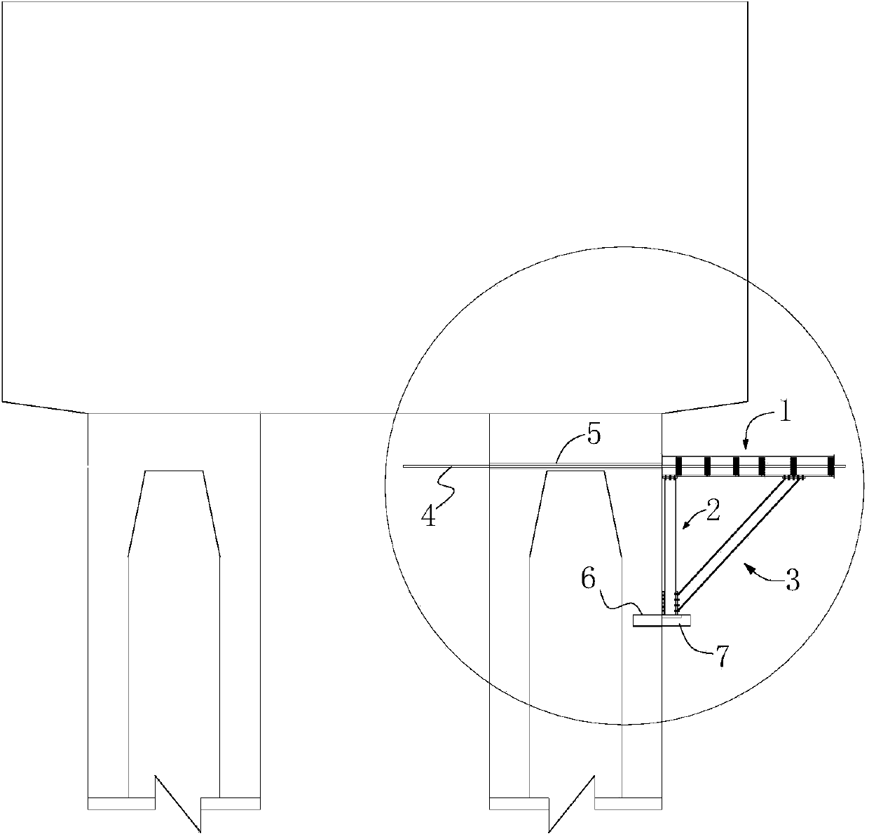
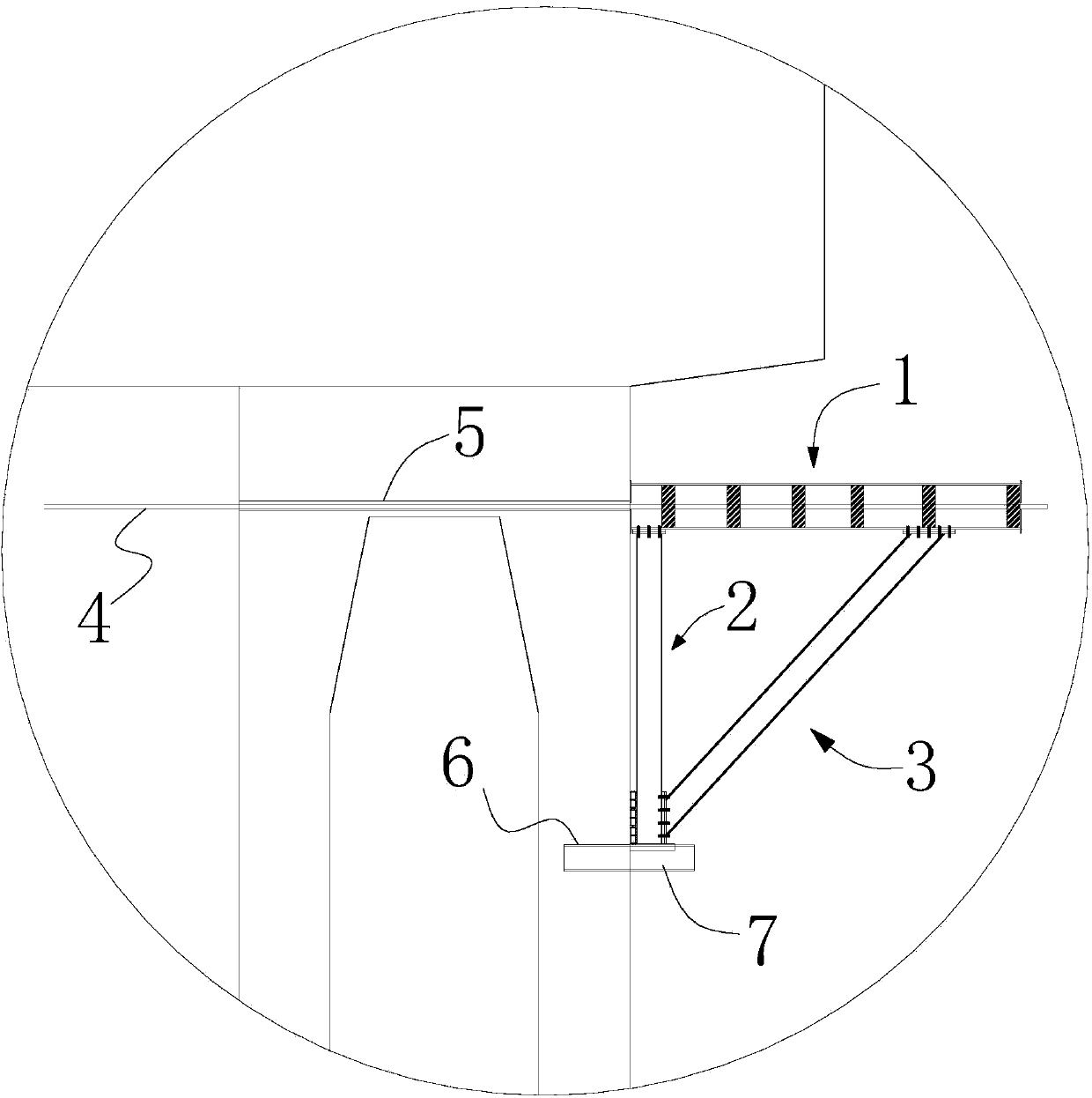
[0051] According to the structural design dimensions of continuous rigid frame (continuous beam) 0# section or straight section, through theoretical calculation, the size of each component of the bracket is reasonably selected; the components are connected by bolts, which is easy to assemble and disassemble; the bottom of the tripod part of the bracket It is connected to the shear bolt by bolts, and the top is fixed by passing through the precision-rolled rebar to the tie rods, and the whole frame is fixed on the pier body.

[0052] Step (1), component making:

[0053]...


PUM


Abstract

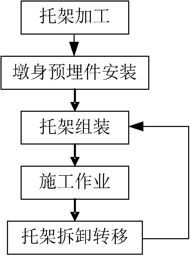
The invention discloses a method for construction of a continuous grid frame 0# section or a linear section through an assembly-type bracket corbel construction device, and particularly relates to a method for construction of a continuous beam linear segment without a floor stand. The method comprises the following steps that (1) a horizontal transverse beam, a vertical supporting mechanism, a slant supporting mechanism, a tie bar, a shear-resisting plug, an embedded steel tube and an embedded steel box are manufactured; (2) the embedded steel tube and the embedded steel box are installed; (3) a corbel tripod is formed by the horizontal transverse beam, the vertical supporting mechanism and the slant supporting mechanism; (4) when the corbel tripod is installed in place, stress is borne by the shearing-resisting plug, the tie bar penetrates through the embedded steel tube and is used for tensioning the horizontal transverse beam and the two ends of the tie bar are fixed; (5) after a bracket is installed, following construction of a bottom die platform and beams is conducted; (6) connection bolts of the tripod are detached, the tripod is put down in a hanging mode and is detached into independent rods which are not assembled, then, the shearing-resistant plug and finish-rolled threaded steel pull bars are detached, and all components are transferred to the next construction point for reassembly or are transferred to a stock for storage.

Description

technical field [0001] The present invention relates to a bridge construction method, in particular to a continuous beam straight section without ground support construction method, more precisely, a continuous rigid structure (continuous beam) No. 0 section or Straight line section without ground support method construction method. Background technique [0002] When the continuous rigid frame (continuous beam) 0# section or straight line section is constructed without floor supports, the design of bracket corbels is involved. The traditional bracket scheme in the prior art is to pre-embed steel plates in the pier body, and weld and assemble on site; or directly embed section steel in the pier body and other conventional methods. The above-mentioned scheme mainly has the following disadvantages: (1) The amount of welding on site is large, the quality of the welds is high, and the control is difficult; or the pier column formwork needs to be opened, which increases the diffi...

Claims


Application Information

Patent Timeline
IPC IPC(8): E01D21/00
Inventor 胡光全陈登云何寿海唐丽茹唐江钟万波杨泉勇李蕾曾长铖王强
Owner CHINA RAILWAY ERJU 1ST ENG
Learn More