Variable Heat/power Ratio Cogeneration System

A variable heat and power cogeneration technology, applied in the charging system, turbine/propellant fuel delivery system, energy industry, etc., can solve the problems of flame disappearance, control delay and increase of NOx emission, etc., to ensure combustion stability, NOx little effect

Active Publication Date: 2014-09-17
MITSUBISHI POWER LTD
View PDF7 Cites 13 Cited by
  • Summary
  • Abstract
  • Description
  • Claims
  • Application Information

AI Technical Summary

Problems solved by technology

In particular, fuel switching is usually completed in a few seconds to tens of seconds, so by detecting the exhaust components with the same degree of time delay, to control the steam flow rate, it may lead to control delay NOx emission increase or flame disappearance

Method used


Image

  • Variable Heat/power Ratio Cogeneration System
  • Variable Heat/power Ratio Cogeneration System
  • Variable Heat/power Ratio Cogeneration System

Examples


Embodiment 1)

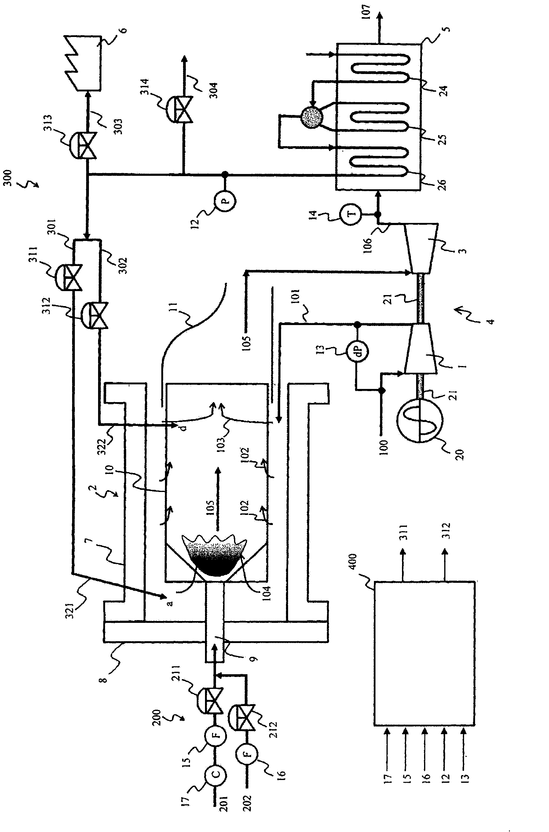
[0075] figure 1 It is a system flowchart showing an example of the configuration of the first embodiment of the heat-to-electricity ratio variable cogeneration system of the present invention. Such as figure 1 As shown, the variable heat-to-electricity ratio cogeneration system is mainly composed of a gas turbine 4 , a waste heat boiler 5 , a generator 20 , and a steam supply system 300 .

[0076] The gas turbine 4 includes a compressor 1 that compresses air 100 to generate high-pressure combustion air; a combustor 2 that combusts compressed air 101 introduced from the compressor 1 and fuel from a fuel system 200 to generate combustion gas 105; and a turbine. 3. It introduces the combustion gas 105 generated by the burner 2 . The rotary shaft of the compressor 1 and the rotary shaft of the turbine 3 are connected by a shaft 21 . In addition, the rotary shaft of the generator 20 driven by the gas turbine 4 to generate electricity is also connected to the rotary shaft of the ...

Embodiment 2)

[0144] A second embodiment of the heat-to-electricity ratio variable cogeneration system of the present invention will be described below using the drawings. Figure 8 It is a system flowchart which shows an example of the structure of the 2nd embodiment of the heat-to-electricity ratio variable cogeneration system of this invention. Figure 8 in, with Figure 1 to Figure 7 The parts shown with the same symbols are the same parts, so detailed description thereof will be omitted.

[0145] Figure 8 The shown second embodiment of the heat-to-electricity ratio variable cogeneration system of the present invention is composed of substantially the same equipment as that of the first embodiment, but differs in the following configurations. In the present embodiment, a regenerator 27 using the low-pressure gas turbine exhaust gas 106 from the turbine 3 as a heat source is provided upstream of the waste heat boiler 5 . The compressed air 101 compressed by the compressor 1 is drawn ...


PUM


Abstract

A variable heat / power ratio cogeneration system is provided, which is capable of suppressing the amount of NOx emission to the minimum level while ensuring the stability of combustion of a gas turbine combustor even when the ratio of gasification gas to be used to a normal fuel (such as natural gas or light fuel oil) to be used is changed or the composition of the gasification gas fuel are changed. The variable heat / power ratio cogeneration system includes: a first steam system (301) that injects extra steam on the upstream side of a flame zone with respect to the flow of combustion gas in the combustor (2); a second steam system (302) that is branched from the first steam system (301) and injects extra steam on the downstream side of the flame zone with respect to the flow of the combustion gas in the combustor(2); a first steam flow rate control valve (311) capable of controlling the flow rate of the steam to be injected by the first steam system (301); a second steam flow rate control valve (312) capable of controlling the flow rate of the steam to be injected by the second steam system (302); and a controller (400) that controls the first steam flow rate control valve (311) on the basis of the flow rate of the gasification gas and the flow rate of the normal fuel and controls the second flow rate control valve (312) on the basis of a demanded steam amount necessary for a steam consumption facility.

Description

technical field [0001] The invention relates to a heat and power cogeneration system with variable heat and electricity ratio. Background technique [0002] A heat-to-electricity ratio variable cogeneration system that provides heat and electricity and can change the heat-to-electricity ratio according to the required demand ratio of heat and electricity is expected as a high-efficiency distributed power supply with little energy loss. With the following invention, in this heat-to-electricity ratio variable cogeneration system, in order to prevent the increase of NOx and unburned components, maintain low NOx operation and high combustion efficiency in the full load range, two burners are equipped with steam The injection system measures the concentration of NOx and the concentration of unburned components in the exhaust gas, and controls the water vapor flow rate of each of the above-mentioned two systems according to the concentration (for example, refer to Patent Document ...

Claims


Application Information

Patent Timeline
Patent Type & Authority Applications(China)
IPC IPC(8): F23L7/00F23N5/00
CPCF01K17/025F01K13/025F02C9/40F01K7/165Y02E20/14Y02P80/15
Inventor 小金泽知己阿部一几
Owner MITSUBISHI POWER LTD
Why Eureka
Try Eureka