
Turbidimeter and liquid analysis equipment

A liquid analysis, turbidimeter technology, applied in the direction of analyzing materials, material analysis by optical means, measuring devices, etc., can solve the problems of dislocation, unsafe, unsanitary and other problems of test results, to improve efficiency, ensure accuracy, The effect of quick detection

Active Publication Date: 2014-09-17
GENRUI BIOTECH INC
View PDF5 Cites 3 Cited by
  • Summary
  • Abstract
  • Description
  • Claims
  • Application Information

AI Technical Summary

Problems solved by technology

The method of manually judging the urine turbidity requires the test personnel to be in close contact with the urine sample, which is unhygienic, unsafe, and low in efficiency. Moreover, when a large number of urine samples need to be tested, the test personnel manually take out the sample for observation and record the turbidity. It is very easy to mistake the sequence of urine samples before and after, resulting in serious accidents of dislocation of test results.
[0004] At present, there are also liquid turbidity equipment, but this liquid turbidity equipment cannot perform continuous and rapid detection on batches of urine samples in hospitals, and the traditional liquid turbidity equipment also has the following shortcomings:
[0005] 1. Traditional liquid turbidity equipment cannot detect trace liquid samples;
[0006] 2. The liquid turbidity equipment with reliable performance needs to collect and calculate the transmitted light intensity and scattered light intensity of the specimen. Traditional photoelectric converters, digital-to-analog conversion circuits and signal shielding measures all result in a relatively large volume of the turbidimeter. Difficult to integrate and work with medical automated testing instruments;
[0007] 3. No matter whether the traditional liquid turbidity equipment adopts the input type or the online circulation detection mode, it cannot meet the requirements of continuous detection of large batches of samples in hospitals and the simultaneous elimination of cross-contamination between samples.

Method used


Image

  • Turbidimeter and liquid analysis equipment
  • Turbidimeter and liquid analysis equipment
  • Turbidimeter and liquid analysis equipment

Examples


Embodiment Construction

[0030] The present invention will be described in detail below in conjunction with the accompanying drawings and embodiments.

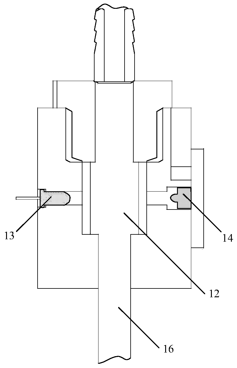
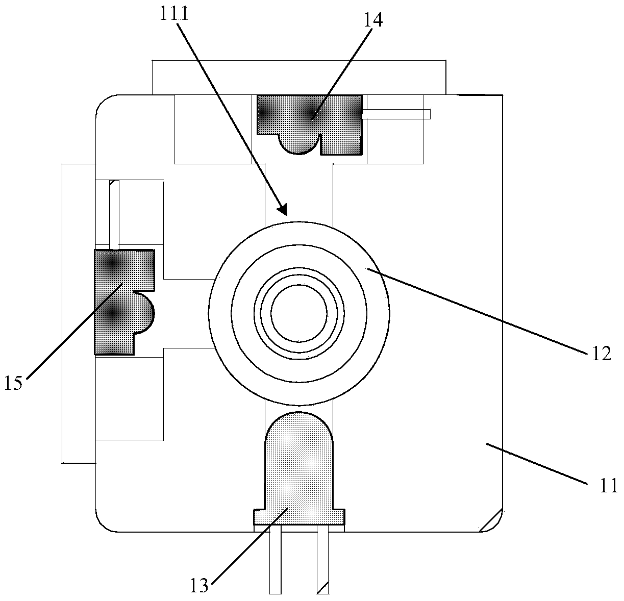
[0031] see figure 1 , figure 2 and image 3 . The turbidity meter includes a housing 11 , a transparent container 12 , a light emitting unit 13 , a first photoelectric conversion unit 14 , a second photoelectric conversion unit 15 , a sampling tube 16 and a processing unit (not shown in the figure).

[0032] A sealed space 111 is disposed inside the housing 11 , specifically, the housing 11 encloses the sealed space 111 , wherein external light cannot enter the sealed space 111 . The transparent container 12 is arranged in the sealed space 111. The surroundings of the transparent container 12 are transparent, and light can pass through the surroundings. In the embodiment of the present invention, the transparent container 12 is a quartz tube. Of course, it is not limited here that the transparent container 12 is only quartz. Tube, in other altern...


PUM

PropertyMeasurementUnit
lengthaaaaaaaaaa
lengthaaaaaaaaaa
lengthaaaaaaaaaa

Abstract

The invention discloses a turbidimeter and liquid analysis equipment. The turbidimeter comprises a shell, a transparent container, a sample absorption pipe, a luminous unit, at least one first photoelectric conversion unit, at least one second photoelectric conversion unit and a processing unit, wherein sealed space is formed in the shell; the transparent container is arranged in the sealed space; one end of the sample absorption pipe is connected with the transparent container, and the other end of the sample absorption pipe extends out of the shell; the luminous unit is arranged in the sealed space and can emit light to the transparent container; the at least one first photoelectric conversion unit and the at least one second photoelectric conversion unit are arranged in the sealed space; the at least one first photoelectric conversion unit receives directly emitted light emitted by the luminous unit and converts the received directly emitted light into a first electric signal; the at least one second photoelectric conversion unit receives scattered light which is emitted by the luminous unit, penetrates through the transparent container and is scattered, and converts the received scattered light into a second electric signal; the processing unit calculates the turbidity of measured liquid according to the first electric signal and the second electric signal. Due to the mode, the turbidimeter can quickly detect the turbidity of the liquid.

Description

technical field [0001] The invention relates to the technical field of liquid detection, in particular to a turbidity meter and liquid analysis equipment. Background technique [0002] A turbidimeter is a device used to detect the turbidity of a liquid, where the turbidity of the liquid is due to the insoluble suspended matter contained in the liquid. [0003] In the medical field, it is often necessary to detect the turbidity of a patient's urine to determine the condition of the patient. At present, the method for detecting the turbidity of urine is to observe manually by inspectors, and judge the turbidity of urine according to the observation results. The method of manually judging the urine turbidity requires the test personnel to be in close contact with the urine sample, which is unhygienic, unsafe, and low in efficiency. Moreover, when a large number of urine samples need to be tested, the test personnel manually take out the sample for observation and record the tu...

Claims


Application Information

Patent Timeline
Patent Type & Authority Applications(China)
IPC IPC(8): G01N21/17G01N21/03
Inventor 夏峰冯尧胡津刘玉芬安培
Owner GENRUI BIOTECH INC
Learn More