

MANUFACTURABILITY OF ePTFE LAMINATED MEMBRANES
A laminated film and reinforcement layer technology, applied in sustainable manufacturing/processing, final product manufacturing, climate sustainability, etc., can solve problems such as time-consuming cost, complex fuel cell components, etc., to increase process efficiency and increase inhalation speed effect
- Summary
- Abstract
- Description
- Claims
- Application Information
AI Technical Summary
Problems solved by technology
Method used
Image

Examples
example 1
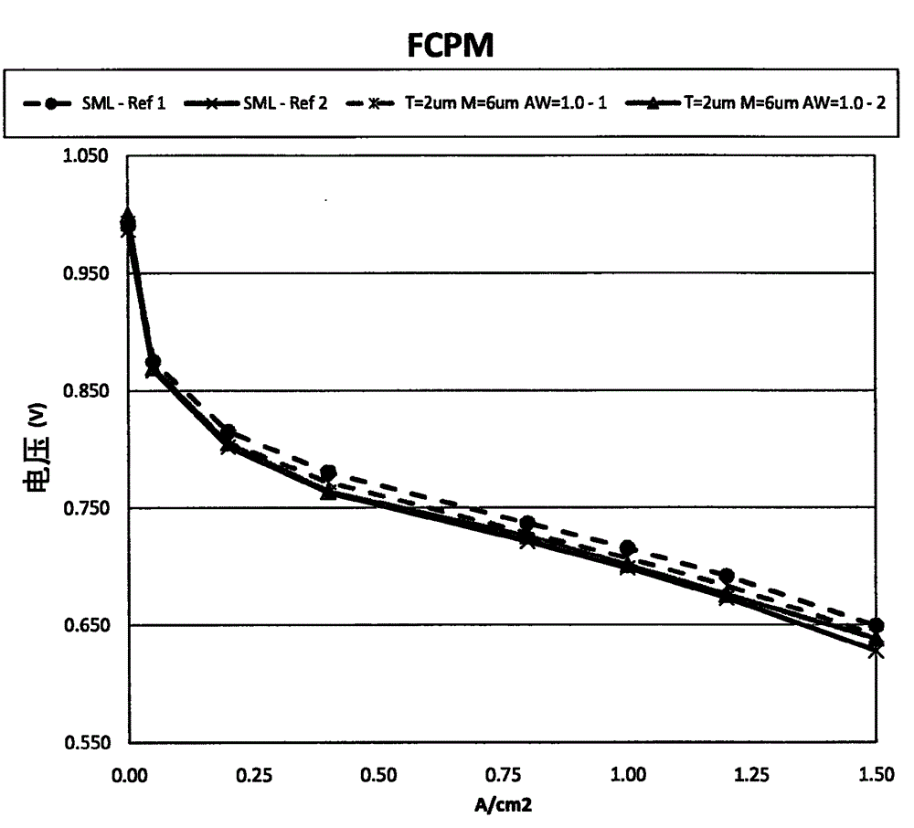
[0120] comparison example
[0121] The cathode ink was prepared by adding 11.69 g of 30% Pt alloy catalyst (supplied by Tanaka Kikinzoku International) and 1080 g of 5 mm spherical zirconia grinding media to the first 500 ml polyethylene bottle. In a second 250 ml polyethylene bottle, 13.02 g of 900 equivalent weight (EW) ionomer (28 wt% solids, 42 wt% ethanol, 30 wt% water) and 5.79 g of 700 EW ionomer (20.5 wt% solid, 79.5 wt% water) and 64.8 g of ethanol, 38.52 g of water, and 1.16 g of 26.7 wt% oleamide, 55 wt% n-propanol, and 18.3 wt% aqueous solution, and the contents were stirred for about 15 minutes . The ionomer solution from the second bottle was then added to the catalyst and milling media in the first bottle. The first bottle was then placed on the ball mill and spun at 145 RPM for 72 hours.
[0122] A 125 ml polyethylene bottle was prepared by adding 38.76 g of 650 EW ionomer dispersion (20.4 wt% solids, 47.8 wt% water and 31.8% ethanol), 28.79 g of ethanol and...
example 2
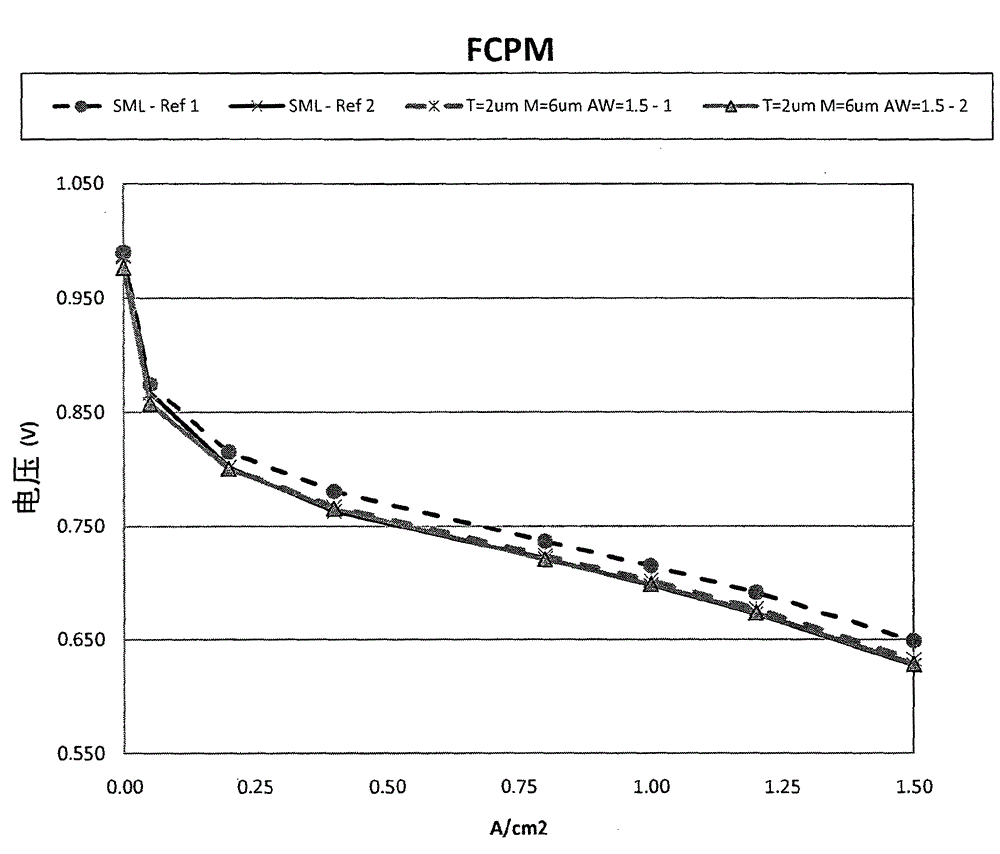
[0125]To demonstrate the improved manufacturability of the presented method compared to Example 1, by adding 11.69 g of 30% Pt alloy catalyst (supplied by Tanaka Kikinzoku International) and 1080 g of 5 mm spherical zirconia ground to the first 500 ml polyethylene bottle medium to prepare cathode ink. In a second 250 ml polyethylene bottle, 13.02 g of 900 equivalent weight (EW) ionomer (28 wt% solids, 42 wt% ethanol, 30 wt% water) and 5.79 g of 700 EW ionomer (20.5 wt% solid, 79.5 wt% water) and 64.8 g of ethanol, 38.52 g of water, and 1.16 g of 26.7 wt% oleamide, 55 wt% n-propanol, and 18.3 wt% aqueous solution, and the contents were stirred for about 15 minutes . The ionomer solution from the second bottle was then added to the catalyst and milling media in the first bottle. The first bottle was then placed on a ball mill and spun at 145 RPM for 72 hours to form a catalyst ink fluid.
[0126] The first was prepared by adding 78.92 g of 650 EW ionomer dispersion (20.4 wt% ...
example 3
[0131] To demonstrate the applicability of the presented method to both cathode and anode electrodes, 6.62 g of 20%Pt graphitized Vulcan catalyst (supplied by Tanaka Kikinzoku International) and 520 g of 5 mm spherical Zirconia grinding media to prepare the anode ink fluid. In a second 250 ml polyethylene bottle, add 22.53 g of 900 equivalent weight (EW) ionomer (28 wt% solids, 42 wt% ethanol, 30 wt% water), 20.75 g of ethanol, 13.72 g of water and 1.39 g 26.7 wt% oleamide, 55 wt% n-propanol and 18.3 wt% aqueous solution and stir the contents for about 15 minutes. The ionomer solution from the second bottle was then added to the catalyst and milling media in the first bottle. The first bottle was then placed on a ball mill and spun at 125 RPM for 72 hours.
[0132] The second was prepared by adding 78.92 g of 650 EW ionomer dispersion (20.4 wt% solids, 47.8 wt% water and 31.8% ethanol), 34.21 g of ethanol and 1.87 g of water to a 250 ml polyethylene bottle and allowed to mix...
PUM
| Property | Measurement | Unit |
|---|---|---|
| Thickness | aaaaa | aaaaa |
| Dry thickness | aaaaa | aaaaa |
| Dry thickness | aaaaa | aaaaa |
Abstract
Description
Claims
Application Information