Wire processing device, wire processing method, storage battery and wire processing and examining device
A technology of processing device and inspection device, applied in the direction of measuring device, battery pack parts, circuit/current collector parts, etc. The effect of short-circuiting the positive and negative electrodes and preventing the core wire from being exposed
- Summary
- Abstract
- Description
- Claims
- Application Information
AI Technical Summary
Problems solved by technology
Method used
Image

Examples
no. 1 approach
[0104] (First embodiment, wire processing device)
[0105] Next, regarding the above-mentioned battery 1, the lead processing device 30 for the positive lead 11 and the negative lead 21 according to the first embodiment will be described.
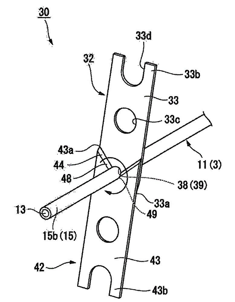
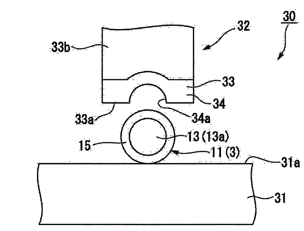
[0106] image 3 It is a schematic configuration diagram of the wire processing apparatus 30 according to the first embodiment, and shows the wire 3 ( image 3 The middle is the state where the positive lead 11) is placed. Here, image 3 The first direction in F coincides with the horizontal direction, and the left side becomes the base end side of the wire 3 in the first direction F, image 3 The right side in the middle becomes the front end side of the wire 3 in the first direction F. In addition, image 3 The up and down direction in is consistent with the vertical up and down direction. Furthermore, install the negative lead 21 (refer to figure 2 ) Is the same as the state where the positive lead 11 is placed, so image 3 The illustration ...
no. 2 approach )
[0138] Figure 8 It is a schematic configuration diagram of the wire processing device 30 according to the second embodiment.
[0139] Next, the wire processing device 30 according to the second embodiment will be described.
[0140] The lead processing device 30 of the first embodiment includes a cutting blade 32 that cuts the positive insulating coating 15 of the positive lead 11, and exposes the positive core wire 13 to the outside between the base end and the tip of the positive lead 11 (see image 3 ).
[0141] In contrast, such as Figure 8 As shown, the wire processing device 30 according to the second embodiment cuts the wire 3 in the first direction F of the cutting blade 32 ( Figure 8 The positive lead 11) shown in the figure is provided with an auxiliary cutting blade 42 interlocked with the cutting blade 32 on the proximal end side, and is different from the first embodiment in this point. In addition, the description of the same constituent parts as those of the first e...
no. 3 approach
[0167] (Third embodiment, wire processing inspection device)
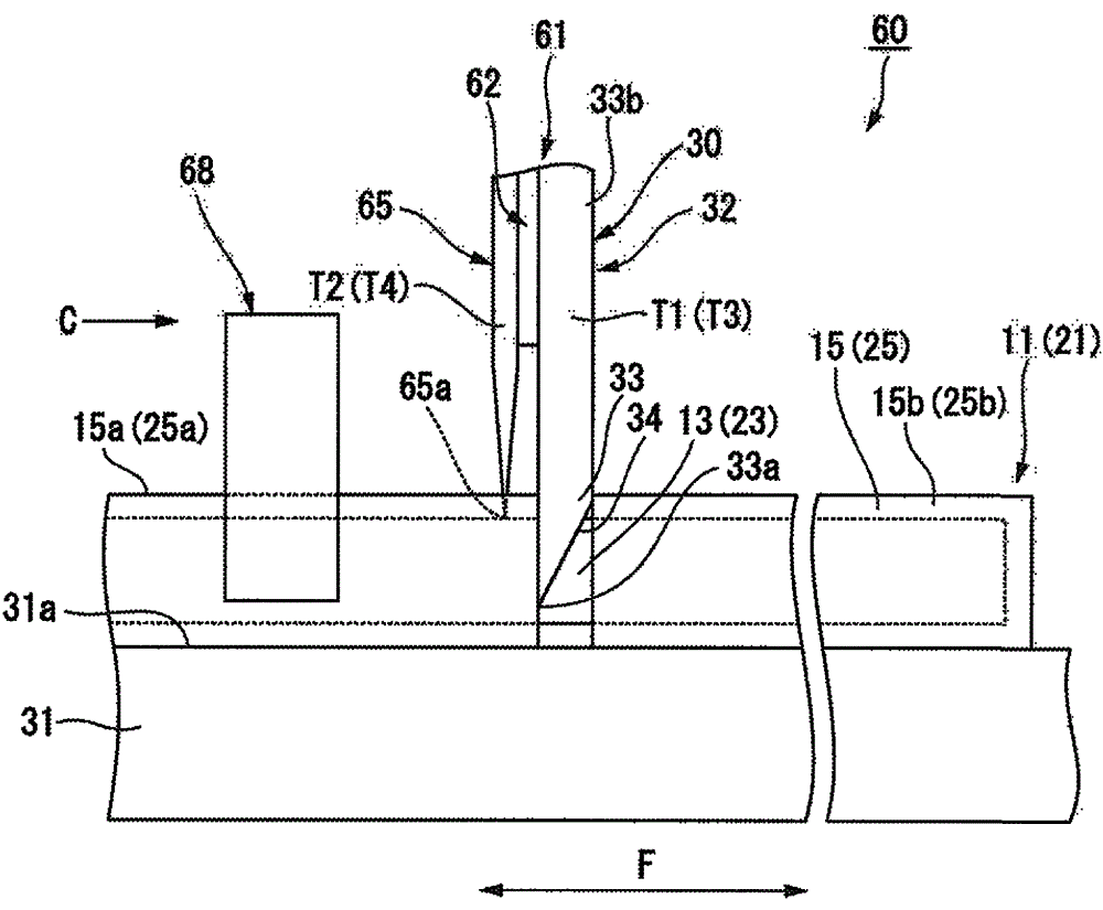
[0168] Next, as a third embodiment, a wire processing inspection device 60 including the wire processing device 30 according to the second embodiment described above will be described.
[0169] The lead processing device 30 of the second embodiment includes a cutting blade 32 and an auxiliary cutting blade 42 that is interlocked with the cutting blade 32 on the proximal side of the positive lead 11 in the first direction F from the cutting blade 32.
[0170] In contrast, the wire processing inspection device 60 according to the third embodiment of the present invention includes the wire processing device 30, and the cutting knife 32 and the auxiliary cutting knife 42 function as the measurement terminals of the ammeter and the voltmeter, respectively. It is different from the second embodiment. In addition, the description of the same components as in the second embodiment will be omitted below, and only the different pa...
PUM
 Abstract
Description
Claims
Application Information
 - R&D
- Intellectual Property
- Life Sciences
- Materials
- Tech Scout
- Unparalleled Data Quality
- Higher Quality Content
- 60% Fewer Hallucinations
Browse by: Latest US Patents, China's latest patents, Technical Efficacy Thesaurus, Application Domain, Technology Topic, Popular Technical Reports.
© 2025 PatSnap. All rights reserved.Legal|Privacy policy|Modern Slavery Act Transparency Statement|Sitemap|About US| Contact US: help@patsnap.com