Rotating electric machine control device and electric power steering apparatus
A technology for rotating electrical machines and control devices, which is applied in the direction of motor control, power steering mechanisms, electric steering mechanisms, etc., and can solve problems such as excessive power supply current flowing out, insufficient output of rotating electrical machines, and error margins, etc.
- Summary
- Abstract
- Description
- Claims
- Application Information
AI Technical Summary
Problems solved by technology
Method used
Image
Examples
no. 1 approach )
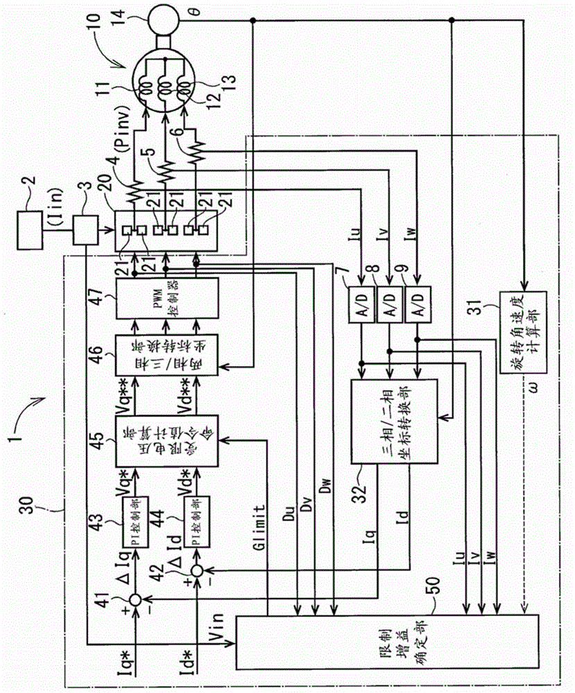
[0020] will refer to figure 1 The rotating electric machine control device 1 according to the first embodiment of the present disclosure will be described. The rotary electric machine control device 1 controls the driving of an electric motor 10 as a rotary electric machine. The rotary electric machine control device 1 can be used, for example, in an electric power steering apparatus that assists a steering operation of a vehicle.
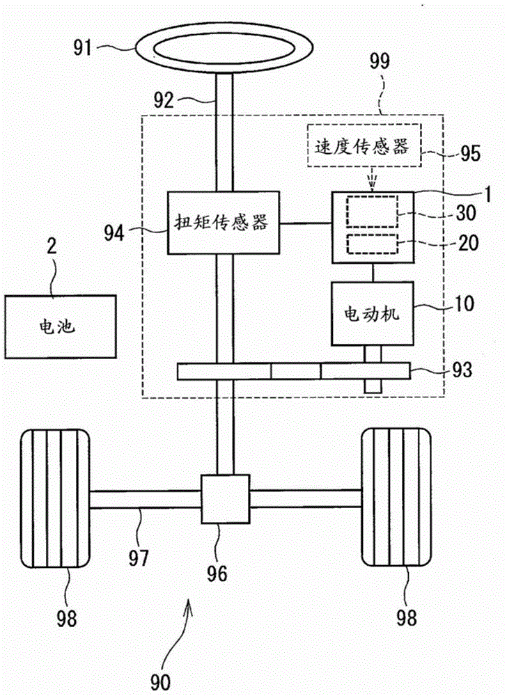
[0021] figure 2 is a diagram showing a steering system 90 including an electric power steering device 99 . The electric power steering device 99 includes a torque sensor 94 . A torque sensor 94 is attached to a steering shaft 92 connected to a steering wheel 91 . The torque sensor 94 detects the steering torque input by the driver to the steering shaft 92 via the steering wheel 91 .
[0022] Attached to one end of the steering shaft 92 is a pinion gear 96 . The pinion gear 96 meshes with the rack shaft 97 . At the end of the rack shaft 97,...
no. 2 approach )
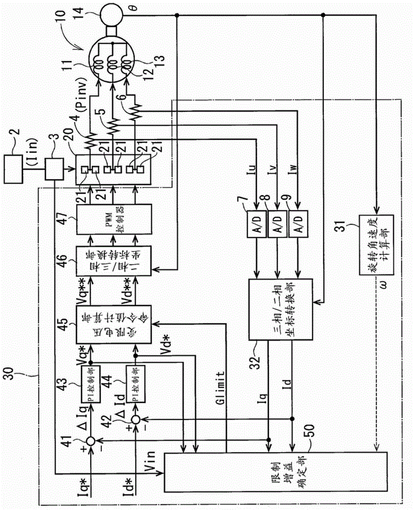
[0060] will refer to image 3 A rotating electric machine control device according to a second embodiment of the present disclosure will be described. The rotating electric machine control device according to the present embodiment has a physical configuration similar to that of the rotating electric machine control device according to the first embodiment. However, the limit gain determination section 50 according to the present embodiment determines the limit gain Glimit in a manner different from that of the first embodiment.
[0061] In the present embodiment, the limit gain determination section 50 determines the limit gain Glimit through a series of first to fourth steps described below. In the present embodiment as well, the limit gain determination section 50 repeats the series of first to fourth steps at a predetermined cycle and determines the limit gain Glimit each time.
[0062] In the first step, the limit gain determination section 50 is based on the U-phase cu...
Embodiment approach )
[0083] Parts of the components in the above-described embodiments may be combined unless there is an obstacle. For example, in the first embodiment, a target power supply current may be determined based on a map, or a limited gain may be set as a value that passes a filter.
[0084] In another embodiment, the target power supply current may be determined based on a calculation formula that is not limited to the mapping. In another embodiment, the limited voltage command value is calculated only for the q-axis voltage command value. In this case, only the q-axis component in the supply current is limited. Therefore, when the rotation of the rotary electric machine is important, the rotary electric machine according to the present embodiment is suitable.
[0085] In another embodiment, the rotating electrical machine may be a multi-phase rotating electrical machine other than a three-phase rotating electrical machine. The rotary electric machine control device according to th...
PUM
 Abstract
Description
Claims
Application Information
 - R&D
- Intellectual Property
- Life Sciences
- Materials
- Tech Scout
- Unparalleled Data Quality
- Higher Quality Content
- 60% Fewer Hallucinations
Browse by: Latest US Patents, China's latest patents, Technical Efficacy Thesaurus, Application Domain, Technology Topic, Popular Technical Reports.
© 2025 PatSnap. All rights reserved.Legal|Privacy policy|Modern Slavery Act Transparency Statement|Sitemap|About US| Contact US: help@patsnap.com


