Gear tooth surface shot peening device and method

A shot peening and gear technology, which is applied in the field of gear shot peening devices, can solve the problems of increasing the cost of gear shot peening, increasing tooth root wear, and increasing the cost of gear manufacturing, so as to reduce the cost of gear shot peening and reduce the compressive stress Poor, improve the effect of impact energy

Active Publication Date: 2014-09-24
CRRC QISHUYAN INSTITUTE CO LTD
View PDF7 Cites 8 Cited by
  • Summary
  • Abstract
  • Description
  • Claims
  • Application Information

AI Technical Summary

Problems solved by technology

For the gear addendum circle and dedendum circle, since the spray direction is perpendicular to its surface, the impact energy E exerted by the projectile when it hits the surface 1 =1 / 2·mv 2 (m is the mass of a single projectile, v is the instantaneous velocity when the projectile hits the surface), but for the pitch circle of the gear, the projectile hits at an angle θ, and the impact energy exerted by the projectile when it hits its surface is E 2 =1 / 2·mv 2 · sinθ, therefore, the residual compressive stress formed on the pitch circle surface of the gear is smaller than the residual compressive stress formed on the surface of the addendum circle and the dedendum circle. Due to the existence of the stress difference, micro protrusions will be generated on the outer edge of the tooth tip of the gear, The micro-protrusion will continue to interfere with the tooth root of the gear, increasing the wear of the tooth root and accelerating the failure of the gear
[0005] When the gear is working, its pitch circle will bear the greatest friction and contact fatigue stress. In order to increase the residual compressive stress at the pitch circle of the gear, it is necessary to prolong the shot peening process time, increase the cost of gear shot peening, and may cause gear tooth root and tooth tip overspray problems
For gears that use the shot peening process as the final process, an additional forming process is required to remove the micro-protrusions on the outside of the tooth top, which increases the manufacturing cost of the gear

Method used


Image

  • Gear tooth surface shot peening device and method
  • Gear tooth surface shot peening device and method
  • Gear tooth surface shot peening device and method

Examples


Embodiment Construction

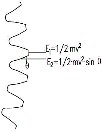
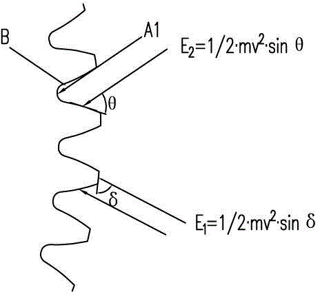
[0027] Such as figure 1 As shown, it is a schematic diagram of a conventional gear shot peening method, and the projectile projection direction is perpendicular to the tooth top of the gear. For the gear addendum circle and dedendum circle, since the spray direction is perpendicular to its surface, the impact energy E exerted by the projectile when it hits the surface 1 =1 / 2·mv 2 (m is the mass of a single projectile, v is the instantaneous velocity when the projectile hits the surface), but for the pitch circle of the gear, the projectile hits at an angle θ, and the impact energy exerted by the projectile when it hits its surface is E 2 =1 / 2·mv 2 · sinθ, therefore, the residual compressive stress formed on the pitch circle surface of the gear is smaller than the residual compressive stress formed on the surface of the addendum circle and the dedendum circle. Due to the existence of the stress difference, micro protrusions will be generated on the outer edge of the tooth tip...


PUM


Abstract

The invention discloses a gear tooth surface shot peening device and method. The gear tooth surface shot peening device comprises two spraying nozzle fixing rods arranged side by side, each spraying nozzle fixing rod is provided with at least two spraying nozzles, the orientations of the spraying nozzles installed on the two spraying nozzle fixing rods are in an intersecting state, and a spraying nozzle distance adjustment device is arranged between the two spraying nozzle fixing rods. The gear tooth surface shot peening method comprises the steps that two bundles of projectiles are shot to a gear tooth from two sides of the gear tooth of a gear in an intersecting mode, the projectiles are shot at an angle delta relative to the top of the gear, and the angle delta ranges from 20 to 80 degrees. At the time, one bundle of projectiles are shot at an angle theta relative to one side of the gear tooth and the pitch circle position of the gear tooth, and the other bundle of projectiles are shot at an angle theta relative to the other side of the gear tooth and the pitch circle position of the gear tooth. The gear tooth surface shot peening device and method can improve surface residual press stress of the pitch circle position of the gear, shorten shot peening time and prevent micro protrusions from being generated on the outer side of the top of the gear tooth.

Description

technical field [0001] The invention relates to a gear shot peening strengthening device and method, in particular to a gear tooth surface shot peening strengthening device and method. Background technique [0002] Gears are important components for power transmission and movement. During work, the surfaces of their meshing teeth will bear strong friction and contact fatigue stresses of both rolling and sliding. Fatigue and wear are the main modes of failure of gear parts. In order to improve the bending fatigue strength of the gear and increase the life of the gear, a layer of residual compressive stress layer can be introduced on the surface of the gear through the shot peening process. [0003] Shot peening mainly relies on the impact of high-speed projectiles on the surface of parts to cause elastic-plastic deformation, resulting in favorable changes such as residual compressive stress, work hardening and microstructure refinement, so as to improve the surface fatigue pe...

Claims


Application Information

Patent Timeline
Patent Type & Authority Applications(China)
IPC IPC(8): C21D7/06
Inventor 陈强刘康冉雄涛魏佳顺
Owner CRRC QISHUYAN INSTITUTE CO LTD
Why Eureka
Try Eureka