Wired geomagnetic guide while drilling and its measurement method

A measurement-while-drilling and guiding instrument technology, applied in construction and other directions, can solve the problems of shallow penetration depth, inability to meet the construction requirements of long-distance and large-depth guided drilling, and short penetration distance, achieving high measurement accuracy and easy popularization and application. Prospect, good construction effect

Active Publication Date: 2017-03-15
HENAN HUABEI ENG TECH CO LTD
View PDF8 Cites 1 Cited by
  • Summary
  • Abstract
  • Description
  • Claims
  • Application Information

AI Technical Summary

Problems solved by technology

[0004] The purpose of the present invention is to overcome the shortcomings of the existing wireless guidance system, which has shallow penetration depth and short penetration distance, and cannot meet the current long-distance and large-depth guidance drilling construction requirements.

Method used


Image

  • Wired geomagnetic guide while drilling and its measurement method
  • Wired geomagnetic guide while drilling and its measurement method
  • Wired geomagnetic guide while drilling and its measurement method

Examples


Embodiment 1

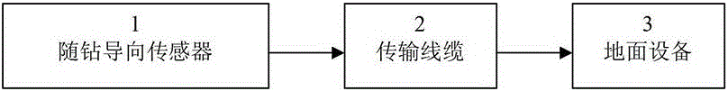
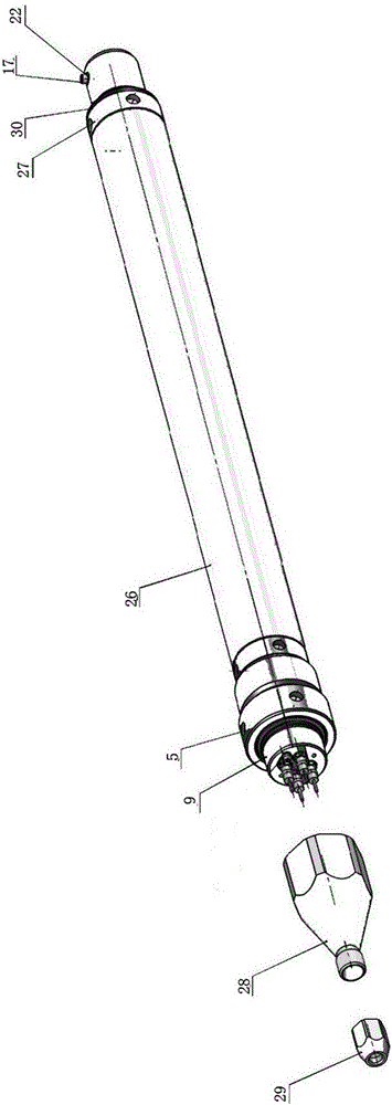
[0041] Embodiment 1: see Figure 1-Figure 7The wired geomagnetic guide while drilling includes two parts: measurement while drilling and ground equipment. The two parts of measurement while drilling and ground equipment communicate through cables. The measurement while drilling part includes the probe of the guide while drilling. The probe of the guide while drilling The upper joint 9 is provided with an inner cavity, and its front end is sealed with a single-core sealing plug 25, and its rear end is connected with a transformer shell, and the cable is connected to the transformer 23 installed in the transformer shell after passing through the upper joint inner cavity from the single-core sealing plug 25; The rear end of the transformer casing is connected with a circuit skeleton 4, and circuit boards 1 and 2 are installed in the connection area between the transformer casing and the circuit skeleton; in the circuit skeleton 4, three directions perpendicular to each other are r...

Embodiment 2

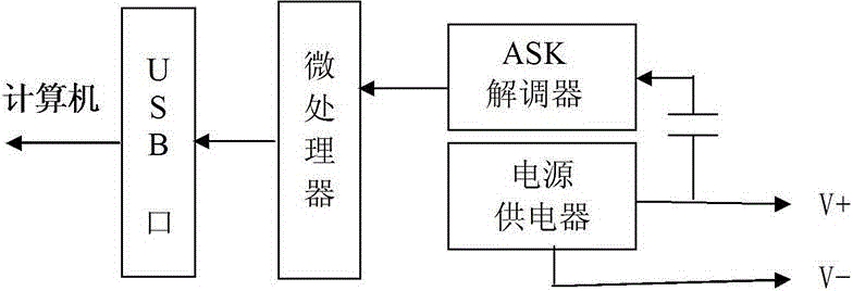
[0042] Example 2: see figure 1 , figure 2 , Figure 8-Figure 11 , The wired geomagnetic guidance-while-drilling measurement method includes two parts: the measurement-while-drilling measurement and the ground equipment, and the communication between the two parts is through a cable, and the communication method is ASK modulation. The measurement while drilling part, that is, the guide probe while drilling, adopts aerospace solid-state inertial navigation technology, and its measurement principle is based on two coordinate systems, namely, the reference coordinate system of the instrument and the measurement coordinate system. The reference coordinate system is established by the gravitational field G of the earth and the geomagnetic field M. The measurement coordinates of the instrument are three sets of sensitive elements installed in the probe of the guide while drilling (each set of sensitive elements contains a magnetic sensor and a gravity accelerometer). Orthogonal mo...


PUM


Abstract

The invention provides a wired geomagnetic guide while drilling and a measurement method, which uses the earth's gravitational field and geomagnetic field as reference points to establish a three-dimensional reference coordinate system, and uses inertial devices such as quartz flexible gravity accelerometers and fluxgate magnetometers as reference points. The measurement-while-drilling sensor calculates the drilling azimuth, pitch angle and drill face angle according to the measurement data of the measurement-while-drilling sensor. The special software package for the wired geomagnetic guidance instrument is used for engineering design before drilling. trajectory, and calculate and process the steering data, guide the drilling trajectory to track the design trajectory, record and print the drilling trajectory data table. The invention adopts ground power supply, the measurement data of the guiding sensor is transmitted by the cable, the measurement accuracy is high, the guiding is accurate, and the depth and distance of directional crossing are not limited, and it can meet the construction requirements of long-distance and large-depth guiding drilling.

Description

technical field [0001] The invention relates to a wired geomagnetic directional drilling system in a long-distance and large-depth directional crossing project, in particular to a measuring instrument based on a quartz flexible gravity accelerometer and a fluxgate magnetometer as a sensitive element for guiding and its measurement method. Background technique [0002] In the directional crossing project, through the wired geomagnetic guided drilling system, the construction personnel can accurately know the depth, position, pitch angle, drilling azimuth and face angle of the current underground drill bit. By controlling the depth, position, pitch angle, drilling azimuth and drill face angle of the underground drill bit, the construction personnel can accurately control the steering drill to track the pre-designed drilling trajectory and realize directional crossing. [0003] The depth and position of the underground drill bit are accurately calculated by the portable comput...

Claims


Application Information

Patent Timeline
Patent Type & Authority Patents(China)
IPC IPC(8): E21B47/0228
Inventor 朱永光刘鹤玲李英林马宸
Owner HENAN HUABEI ENG TECH CO LTD
Why Eureka
Try Eureka