
Electric control uniset fuel injection pump for diesel engine

A technology for diesel engines and fuel injection pumps, which is applied to fuel injection pumps, fuel injection pumps, engine control, etc., and can solve problems such as short service life, easy wear, and poor recovery accuracy

Inactive Publication Date: 2014-09-24
SHANDONG XINYA IND
View PDF8 Cites 3 Cited by
  • Summary
  • Abstract
  • Description
  • Claims
  • Application Information

AI Technical Summary

Problems solved by technology

At present, the domestic air-cooled single-cylinder diesel engine is due to the congenital reasons of the structural design (such as the chute plunger), the pump end pressure is only about 30MPa, the low pump end pressure causes poor spray quality, and the mixed combustion of fuel and air is not sufficient, resulting in a large amount of Particles and smog pollute the environment. Mechanical fuel injection pumps and governors are used. The noise of the diesel engine is large. The speed regulation accuracy of the governor is not high, and the recovery accuracy is poor. The oil advance angle cannot be continuously adjusted
The spiral groove structure gauge of the plunger is easy to wear and has a short service life
At present, advanced electronically controlled single-cylinder pumps are developed in the world, but the structure of the prepared electronically controlled single-cylinder pumps is relatively complicated, the manufacturing cost is high, and it is difficult to popularize

Method used


Image

  • Electric control uniset fuel injection pump for diesel engine
  • Electric control uniset fuel injection pump for diesel engine
  • Electric control uniset fuel injection pump for diesel engine

Examples


Embodiment Construction

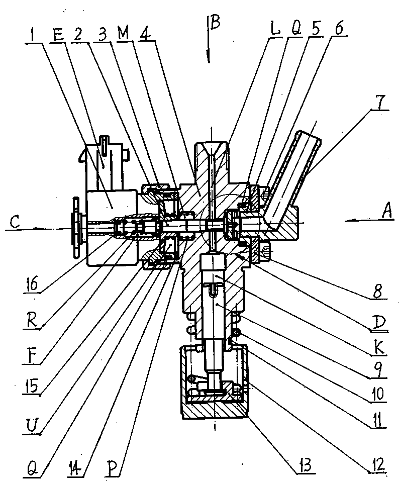
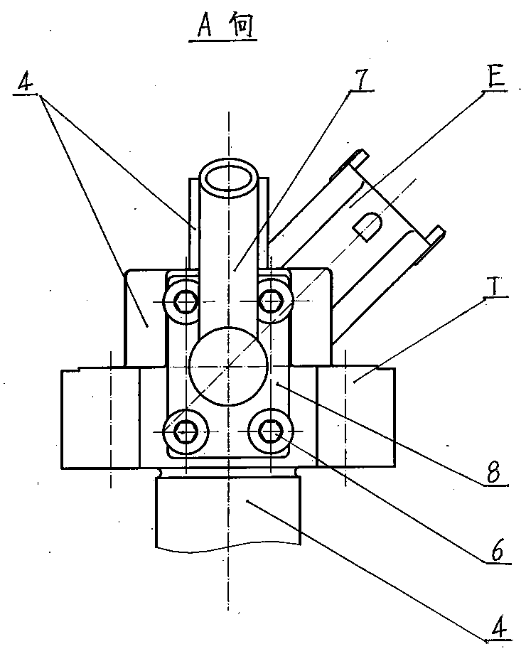
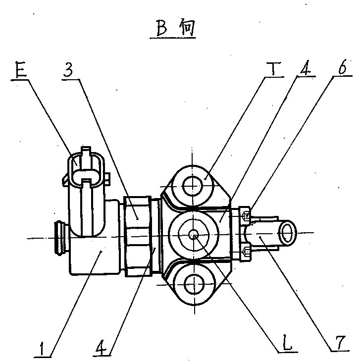
[0018] Specific embodiments of the present invention will be described below in conjunction with the accompanying drawings.

[0019] refer to figure 1 , figure 2 , image 3 , Figure 4, the present invention is composed of a plunger assembly, a solenoid valve assembly, and an oil supply assembly installed on the pump body 4, and the oil supply is controlled by an electric control system. L, with electromagnet installation hole M and low-pressure oil supply chamber N respectively opened on both sides, connected through connecting middle hole H, and vertically connected with high-pressure oil hole L; plunger assembly includes plunger 9, plunger spring 10, under spring Seat 13, push rod body 12, the front section of plunger 9 is fitted in the plunger cavity K of pump body 4, and the rear section sets plunger spring 10 to connect spring lower seat 13, and is embedded in push rod body 12; The valve assembly includes an electromagnet 1, an armature 15, a valve core 2, a return ...


PUM


Abstract

Disclosed is an electric control uniset fuel injection pump for a diesel engine. According to the electric control uniset fuel injection pump for the diesel engine, a pump body plunger cavity is communicated with a high-pressure oil hole, an electromagnetic installation hole and a low-pressure oil supply cavity are formed in the two lateral sides, are communicated through a middle connection hole and are perpendicularly communicated with the high-pressure oil hole, the front section of a plunger is assembled in a plunger cavity, the rear section of the plunger is sleeved with a plunger spring and connected with a lower spring base which is embedded in a push rod body, an armature is movably installed in an armature hole of an electromagnet in a sleeved mode, the electromagnet is installed in an electromagnet installation hole, one end of a valve element fixedly installed in the armature hole penetrates through the middle connection hole to extend into the low-pressure oil supply cavity and abut against a lift check block, and the lift check block is connected with an oil inlet pipe. An electric control system is communicated with the electromagnet to control the action of the armature and the valve element, an oil supply system of a traditional fuel injection pump is converted into a fuel injection system featured in time, oil supply timing and quantity are controlled and adjusted precisely, the pressure of the end of the pump is high, oil consumption is low, and noise is low.

Description

technical field [0001] The invention relates to matching parts of a diesel engine, in particular to a single-cylinder fuel injection pump. Background technique [0002] The single-cylinder diesel engine is the basic small power machine in our country. It has played a huge role in China's industrial production and rural economy during the development of more than half a century, especially as the main power source in transportation, irrigation and processing. With the improvement of science and technology and the development of economic construction, the requirements for energy saving and environmental protection of power machinery are becoming increasingly strict. As the heart of a single diesel engine, the fuel injection pump assembly bears the brunt of the increase in the gear level. The traditional mechanical fuel injection pump is composed of plunger coupling, oil outlet valve coupling, adjusting fork parts, oil outlet valve tight seat, plunger spring, etc., by changing ...

Claims


Application Information

Patent Timeline
Patent Type & Authority Applications(China)
IPC IPC(8): F02M51/04F02M59/44F02D1/02
Inventor 鲍慧涛郭莉孟红喜蔡杰华刘瑞华李刚健
Owner SHANDONG XINYA IND
Learn More